Published 01-15-2016, Control # 526-01 3-29
RT540E OPERATOR MANUAL OPERATING CONTROLS AND PROCEDURES
Turntable Lock Control (Pin Type)
The Swing Lock Pin Control Handle (13) (Figure 3-12) is
located beside the front console on the right side of the cab.
The purpose of the swing lock pin is to lock the
superstructure in position directly over the front for pick and
carry loads. When the control handle is pushed down and
the superstructure is directly over the front, the swing lock
pin drops into the socket on the carrier frame, locking the
superstructure in place. When the control handle is pulled
up, the pin is pulled out of the socket, unlocking the
superstructure.
Sensors
There is a Temperature Sensor (12) and a Brightness
Sensor (11) (Figure 3-12). The Brightness Sensor
automatically adjusts the brightness of all displays.
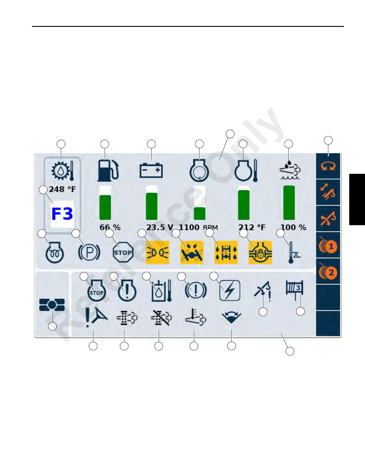
CCS MAIN SCREEN SYMBOLS AND ICONS
1
2 3
4
5
6
28
23 24
25
26
27
21
22
16
17
18
19
20
15
14
13
12
11
10
9
8
7
FIGURE 3-14
29
30
31
Reference Only

 Loading...


