ELECTRIC SYSTEM RT880E SERVICE MANUAL
3-6 Published 11-10-2014, Control # 524-00
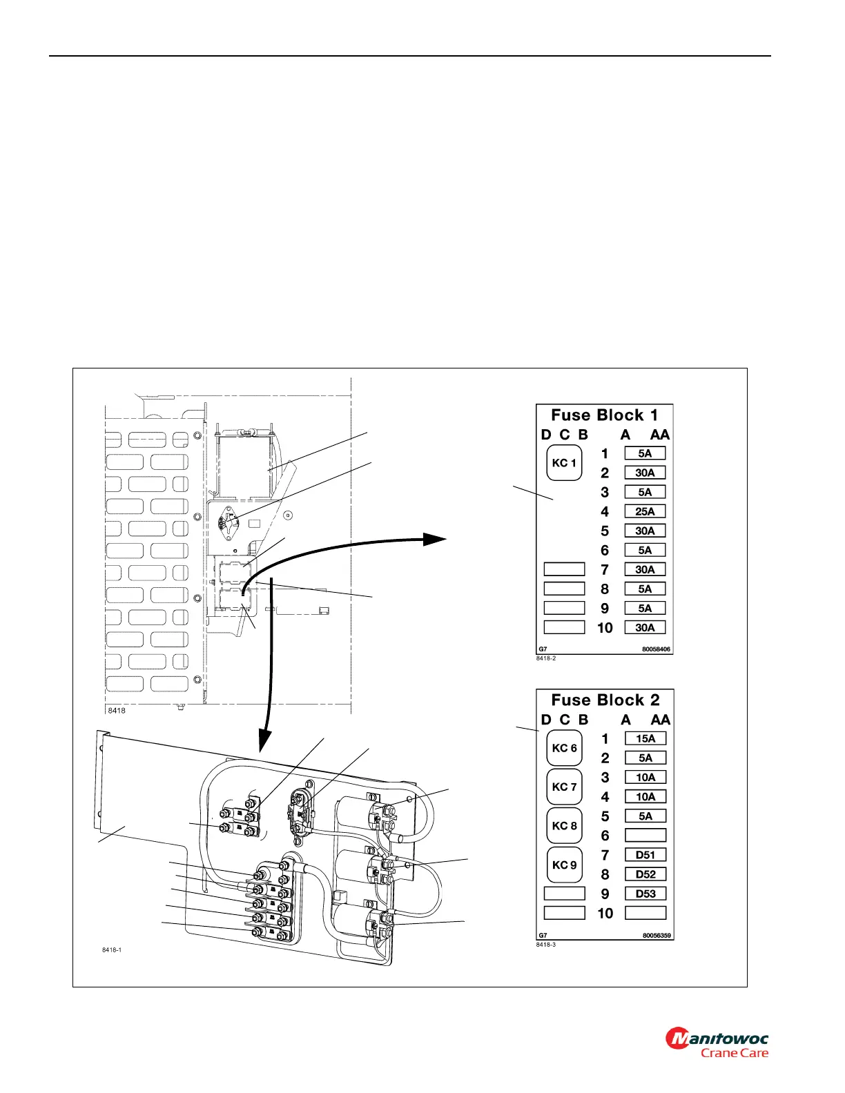
Carrier Electrical Panel
The carrier electrical panel contains the battery disconnect
switch, main power relay, and fuses that control power to the
crane’s entire electrical system. The panel (3) (Figure 3-6) is
located on the fuel tank side of the crane, under the battery
box assembly.
The coil of the main power relay (6) (Figure 3-6) is energized
when the ignition switch is in the RUN or ACC position, or
while the crane’s control system Master Module commands it
to be on, or when the head light, tail lights, hazard lights or
brake lights are activated.
The coil of the start relay (7) (Figure 3-6) is energized when
the batteries are connected, the start message from the
steering column is present, the emergency stop switch is not
activated, the engine is not running, and if the crane is
equipped with a Tier 4 engine, the starter lockout signal from
engine ECM must be present.
The coil of the grid heater relay (8) (Figure 3-6) is energized
when the batteries are connected, the ignition switch is in the
RUN position, and the output from the engine ECM to the
grid heater coil must be energized.
The 250A fuse (10) (Figure 3-6) protects the batteries, the
alternator, and the battery/alternator charge line. The 100A
fuse (9) (Figure 3-6) protects those circuits that receive
power when the battery disconnect switch is closed. The
250A fuse (5) (Figure 3-6) and the three 100A fuses (13, 14,
15) (Figure 3-6) receive power when the main power relay is
energized. The 250A (5) protects the grid heater circuit and
the three 100A fuses (13, 14, 15) protect the main feeds to all
other circuits.
3
4
1
FIGURE 3-6
8
10
11
3
2
9
7
6
15
14
13
12
2
11
16
5

 Loading...


