Grove Published 11-10-2014, Control # 524-00 2-59
RT880E SERVICE MANUAL HYDRAULIC SYSTEM
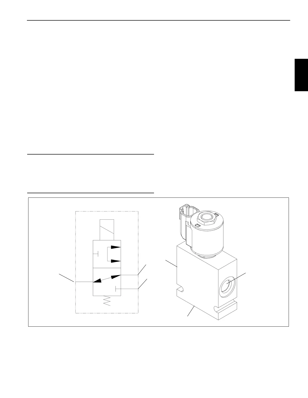
CROSS AXLE DIFFERENTIAL LOCK VALVE
Description
The cross axle differential lock valve Figure 2-32 is mounted
off the carrier bulkhead plate forward of the engine. The
valve is a four-way, two position solenoid valve. The valve is
used to control the application of the crane’s hydraulically
applied and released cross axle differential lock actuators.
Positioning the cab Axle Diff Switch to LOCK shifts the four-
way, two-position solenoid valve so hydraulic oil can flow to
the engage port of the cross axle differential lock actuators,
extending them. When the actuators extend, they engage
the splines on the differential case and the axle shafts to lock
the differential assemblies together.
Positioning the cab Axle Diff Switch to UNLOCK shifts the
four-way, two-position solenoid valve so hydraulic oil can
flow to the disengage port of the actuators, retracting them.
As the actuators retract, they unlock the axles.
Maintenance
Removal
1. Tag and disconnect the electrical connector from the
valve.
2. Tag and disconnect the hydraulic lines attached to the
valve. Cap or plug lines and ports.
3. Remove the two bolts and washers securing the valve to
the frame. Remove the valve.
Installation
1. Secure the valve to the frame with the two bolts and
washers. Torque bolts; refer to Fasteners and Torque
Values, page 1-15 for proper torque value.
2. Connect the hydraulic lines to the valve as tagged during
removal.
3. Connect the electrical connector to the valve as tagged
during removal.
4. Apply and release the cross axle differential lock several
times. Verify the cross axle differential lock holds the
axle from moving when applied so there is no differential
action between the wheels.
5. Check for leaks. Make repairs as needed.
CAUTION
Axle Damage!
Operating the machine with the differentials in the locked
position while maneuvering on improved surfaces may
result and damage to the axles.
FIGURE 2-32
1
3
3
2
1
2
7395-1
7395-2

 Loading...


