Grove Published 11-10-2014, Control # 524-00 4-23
RT880E SERVICE MANUAL BOOM
NOTE: Refer to Section 2 for Lift Cylinder Disassembly
and Assembly procedures. Maintenance not
requiring removal of the cylinder barrels, such as
packing, may be performed without removing the
cylinders from the turntable. However, all disas-
sembly and assembly should be conducted in a
clean dust-free area.
Lift Cylinder Removal
1. Extend and set the outriggers and level the crane.
2. Elevate the boom slightly so that the lift cylinder is
extended approximately 1 ft (0.3 m).
3. Ensure the boom is fully supported by placing blocking
or cribbing under the boom. Rest the boom on the block-
ing or cribbing.
4. Remove the capscrew and washers securing the lift cyl-
inder upper pivot shaft to the boom.
5. Remove the bolt, locknut and shim securing the lift cylin-
der lower pivot shaft to the turntable.
6. Attach an adequate lifting/supporting device to the lift
cylinder.
7. Remove the upper lift cylinder pivot shaft. Activate the
hydraulic system and retract the lift cylinder enough to
clear the upper attach point.
8. Tag and disconnect all the hydraulic lines to the cylinder.
Cap or plug all openings with high pressure fittings.
9. Pull the lower lift cylinder pivot shaft out far enough to
remove the cylinder.
10. Move the lift cylinder to a clean work area.
Disassembly and assembly procedures of the lift cylinder
holding valve, and control valve are provided in Section 2
under Cylinders and Valves respectively.
Lift Cylinder Installation
1. Attach an adequate lifting device to the lift cylinder and
position the cylinder over the attach fitting on the turnta-
ble.
2. Lower the lift cylinder into the attach fittings on the turn-
table and align the lift cylinder bushing with the attach fit-
ting holes.
NOTE: Install pivot shaft with tapped hole on the right side,
side opposite the cab.
3. Install the lift cylinder lower pivot shaft and secure with
the shim, bolt and locknut. Torque bolt; refer to Fasten-
ers and Torque Values, page 1-15 for proper torque
value.
4. Connect the extend and retract hoses to the lift cylinder.
5. Activate the crane’s hydraulic system and align the lift
cylinder rod end with the attach point on the boom.
Secure the upper pivot shaft to the boom with the cap-
screw and washers. Torque capscrew; refer to Fasten-
ers and Torque Values, page 1-15 for proper torque
value.
6. Remove the lifting and supporting devices from the
boom and lift cylinders. Activate the hydraulic system
and check the lift cylinders for proper operation and any
leaks.
7. Lubricate the pivot shafts.
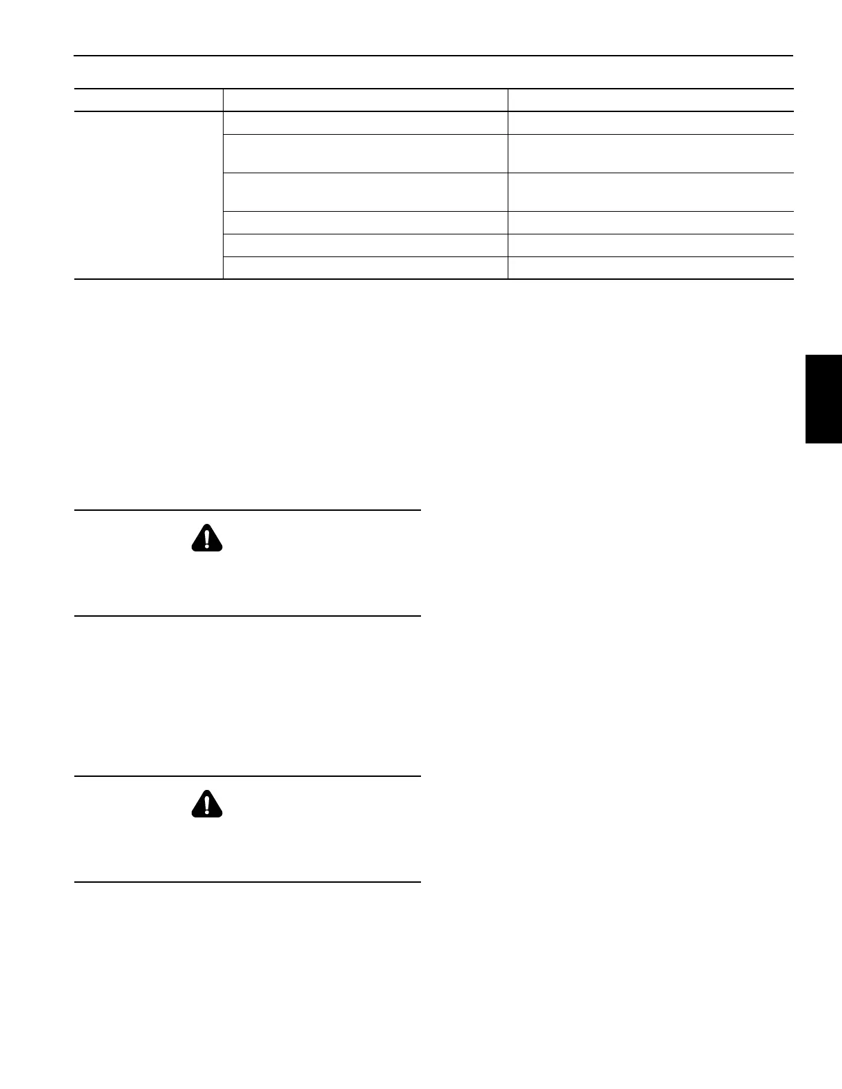
6. Boom will not
lower.
a. Low hydraulic oil. a. Replenish hydraulic oil to proper level.
b. Main relief valve or circuit relief valve
damaged.
b. Repair or replace relief valve.
c. Worn or damaged hydraulic pump
section.
c. Repair or replace pump section.
d. Broken pump shaft. d. Replace pump shaft and seals.
e. Broken pump drive coupling. e. Replace drive coupling.
f. Broken control valve spool. f. Replace control valve.
Symptom Probable Cause Solution
DANGER
Crushing Hazard!
Ensure any blocking or cribbing used is capable of
supporting the boom.
DANGER
Crushing Hazard!
Ensure the lifting/supporting device is capable of
supporting the lift cylinder.

 Loading...


