NATIONAL CRANE Published 03-23-2018 Control # 243-14 4-17
NBT50 OPERATOR MANUAL SET-UP
REMOVABLE COUNTERWEIGHT
The NBT50 is equipped with a single section Removable
Counterweight and the NBT55 is equipped with a two section
Removable Counterweight. Each cast section weighs
3000 lb (1360 kg). The following procedures are applicable
for mounting and stowing the top section or both sections.
Refer to Figure 4-12 for an illustration of the components that
make up the Removable Counterweight.
Mounting the Counterweight
1. Position crane on a firm, level surface.
2. Fully extend and set the outriggers, then level the crane
(see Setting the Outriggers, page 4-2).
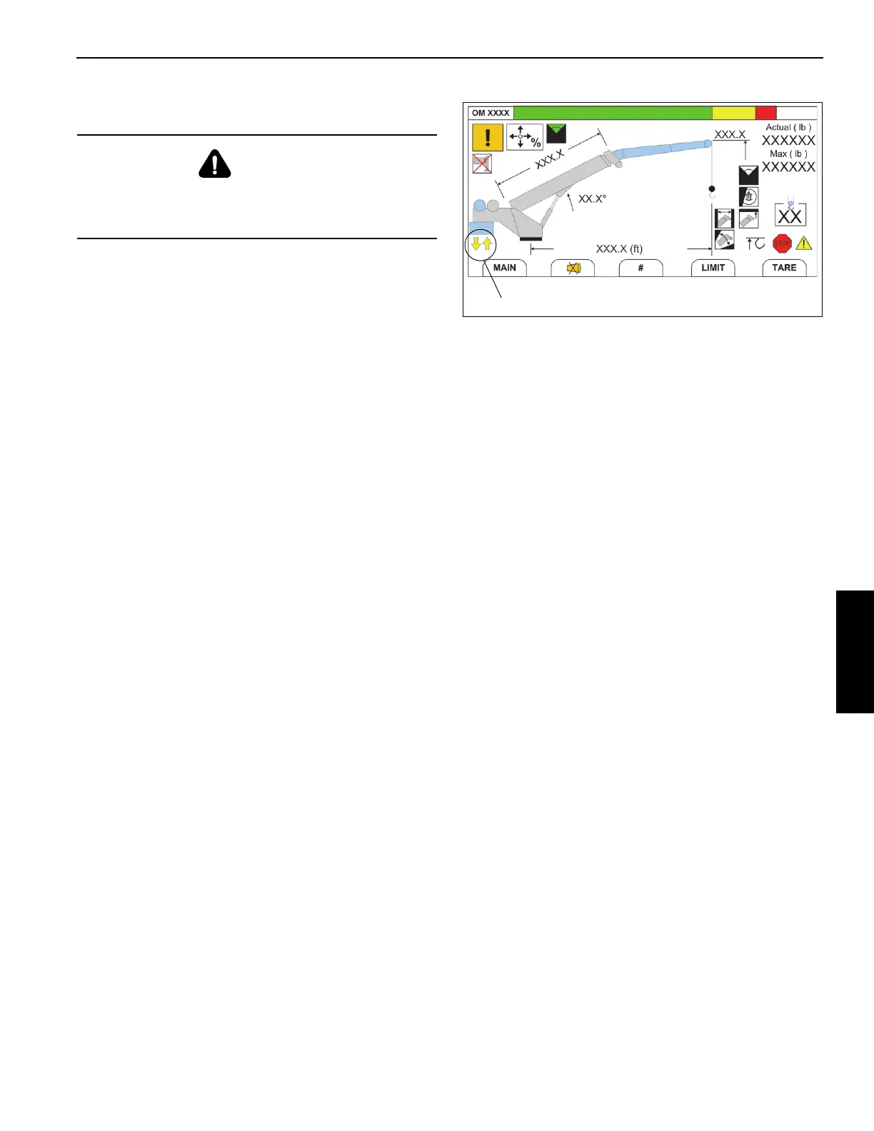
3. Set display in Operator’s Console to the
RCL Operating
Mode Screen (Figure 4-11) (see Section 7, Rated
Capacity Limiter
).
4. While watching the display, rotate superstructure until
Counterweight Removal Slew Position Indicator (yellow
arrows) (1, Figure 4-11) appears in the display, which
indicates the rear of the superstructure is nearly directly
above the Removable Counterweight stowed on the
carrier deck.
Ensure vertical alignment of superstructure to
counterweight by leaving the cab and performing a
visual inspection. If necessary, return to cab and rotate
superstructure until alignment is achieved.
5. Retract left and right pins (5, Figure 4-12) from top of
Removable Counterweight.
6. Remove left and right pins (4, Figure 4-12) from top of
Removable Counterweight.
7. Remove left and right pins (7, Figure 4-12) that secure
counterweight to carrier deck.
If crane is equipped with top and bottom counterweight
sections (1, 2, Figure 4-12) and only the top section is to
be loaded, only remove the left and right pins (6,
Figure 4-12) which secure the top and bottom sections
together; do not remove pins (7, Figure 4-12) that
secure bottom counterweight to carrier deck.
DANGER
Ensure that all mounting pins are properly installed and
locked, during, and after operating the counterweight
removal system.

 Loading...


