CONTROLS AND OPERATING PROCEDURES OPERATOR MANUAL NBT50
3-4 Published 03-23-2018 Control # 243-14
Crane Level Indicators
A bubble level indicator is located inside the cab near the
right side armrest. This indicator provides the operator with a
visual indication for determining how level the crane is when
operating the outriggers. There are two additional level
bubbles located on the lower frame at each ground level
control station.
.
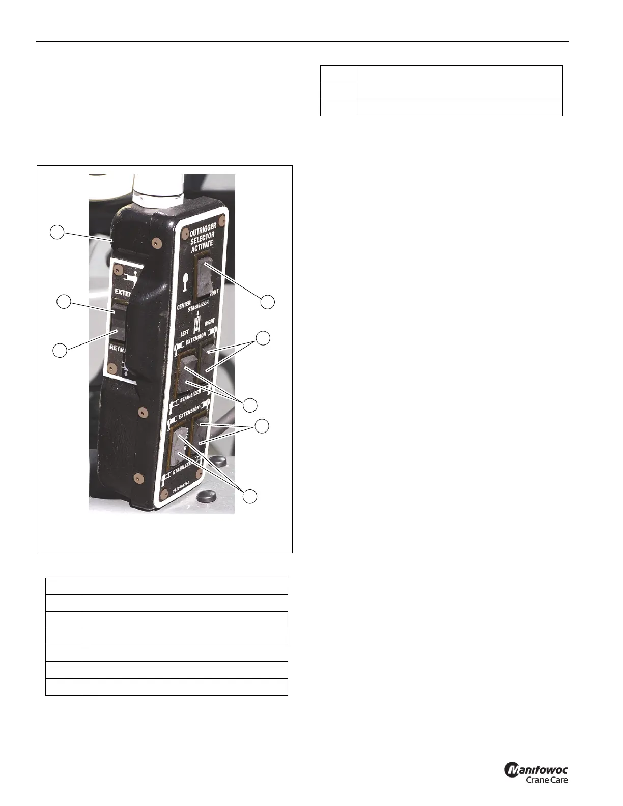
Cab Outrigger Control
The cab hand-held outrigger control (1, Figure 3-1) is stowed
in the cab (Figure 3-4) and is used to control the outriggers
from inside the cab.
Extend/retract Switch
The extend/retract switch (8,7 Figure 3-1) is located on the
side of the outrigger control box and is used in conjunction
with the outrigger selector switches (3,4,5,6 Figure 3-1) to
control the outrigger functions.
Outrigger Selector Switches
There are four outrigger selector switches (3,4,5,6
Figure 3-1) on the outrigger control box. To extend or retract
an outrigger component, first select the component with the
outrigger selector switch (3,4,5,6), then select extend or
retract with the extend/retract switch (7,8 Figure 3-1).
Center Front Stabilizer Switch
The center front stabilizer switch (2 Figure 3-1) is used to
lower and raise the optional center front stabilizer. To operate
the center front stabilizer, press the center front stabilizer
switch toward activate and then press extend/retract switch
(7,8). The center front stabilizer automatically retracts if any
of the other jacks are adjusted and must be reset if lifting is to
be continued.
Ground Station Outrigger Control
The following paragraphs describe the outrigger controls and
indicators (Figure 3-2) found on the ground station outrigger
control panels.
Outrigger Control Panel
There is one outrigger control panel on each side of the
machine frame, as shown in Figure 3-2 and Figure 3-3. The
following details apply to both control panels as indicated.
• The panel on the right side operates the outrigger
beams for that side only.
• The panel on the left side operates the outrigger
beams for that side only.
• The stabilizers (jacks) may be operated from the left
or right side of the unit.
• Each control panel contains a control switch for
raising and lowering the center front stabilizer.
Item Description
1 Hand Held Control
2 Center Front Stabilizer Switch
3 Right Front Extension/Right Front Jack
4 Left Front Extension/Left Front Jack
5 Right Rear Extension/Right Rear Jack
6 Left Rear Extension/Left Rear Jack
7 Retract O/R
8 Extend O/R
Item Description

 Loading...


