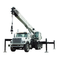
CONTROLS AND OPERATING PROCEDURES OPERATOR MANUAL NBT50
3-2 Published 03-23-2018 Control # 243-14
Operation. . . . . . . . . . . . . . . . . . . . . . . . . . . . . . . 3-24 Crane Remote Control (optional) . . . . . . . . . . . . . 3-25
Crane Remote Control Activation. . . . . . . . . . . . . 3-26
This section contains information on the controls and
operating procedures to include:
• Truck Cab Controls
• Outrigger Controls
• Crane Controls
• Operating Procedures
• Hoist System Operation
• Work Site Location
• Load Chart
• Lifting the Load
• Shutdown and Preparation for Travel
CRANE THEORY OF OPERATION
Crane Software Overview
The NBT50 is equipped with a CAN bus electronic system
that controls the majority of the devices on the crane. This is
a distributed system consisting of several electronic modules
that all perform different functions based on the crane's
software. These modules are all connected together with a
twisted pair of wires that allows all the modules to talk on the
same databus - the CAN bus - to provide the information
about the state of all the devices on the machine. There is a
main module, or “server” module that controls all the other
secondary modules called “client” modules in the system.
The software that describes how the crane should react to
the various switches, sensors, joysticks and pedals is
installed on the server module which then controls the client
modules functions.
When a switch or a pedal is used, an “input” is sent to an
electronic module which monitors any change in value.
When the input has been received and the crane software
logic allows for this to be communicated to the “output”
device, the machine then responds to the operator's “input”.
For example, if the crane operator moves the swing left
joystick to rotate the machine, the “input” from the joystick is
read by the control modules but the crane server module
knows that movement is not allowed unless the swing brake
release switch is activated. So in this example, the swing left
proportional output is not energized and there is no crane
movement.
Getting Started
The NBT50 has several interlocks that must be satisfied
before operating the crane. To operate the crane, the
machine must be started from the crane cab key switch.
Starting the truck from the truck cab will not allow the crane
to operate. There are several interlocks that will prevent the
crane cab key switch from turning on the ignition power
circuit for the truck ignition:
• Lower ground level outrigger panel ESTOP
switches must be released
• Crane Cab ESTOP switch must be released
• Truck ignition key switch must be off
• Hydraulic Suction Shut-off Valve is shut
There is also an interlock that prevents the crane key switch
from starting the truck engine:
• PTO must be engaged
If unable to activate the crane cab key switch, first check the
status of these items and then cycle the crane cab key switch
and try again. These interlocks are designed to ensure that
the crane performs as desired and allow for all the ESTOP
switches to be available for use if needed.
Crane Ignition and Control States
The NBT50 control system consists of many “states” which
describe groups of functions that can or cannot be performed
while in that state. This allows for the machine to operate
several ways when running the truck chassis, the crane, or
radio remote control of the crane. These “states’ can only be
seen through the crane’s diagnostic software program.
Ignition States
Since the crane and the truck chassis both have key
switches, there is interlock logic to only allow one switch to
be active at a time even if both switches are turned ON. The
first switch to be turned to ignition is the controlling key
switch. Here is a summary of the main ignition states:
• Ignition State = 0 (No ignition switch active)
• Ignition State = 1 (Truck ignition switch active)
• Ignition State = 2 (Crane ignition switch active)
To transition between Ignition State = 0 to Ignition State = 2,
the crane cab key switch should be turned to the ignition
position. In order to transition from Crane Ignition to Truck
Ignition, the crane cab key switch must first be turned OFF
and then the truck key switch can be turned to ignition. Both

 Loading...


