NATIONAL CRANE Published 9-26-2018 Control # 646-02 4-19
NTC55 OPERATOR MANUAL SET-UP
c. Release the left and right Counterweight Removal
Cylinder Lower Buttons when cylinders are at the
proper position to pin the counterweight to the
cylinders.
If cylinders and counterweight do not vertically align,
return to cab and swing superstructure until
alignment is achieved.
NOTE: The cylinders can rotate axially when no
counterweight is installed, causing the cylinder pin
holes to not align with holes in counterweight. If this
occurs, rotate cylinder rod using your hand or
counterweight pin.
9. Attach Removable Counterweight to cylinders using
pins (5, Figure 4-12).
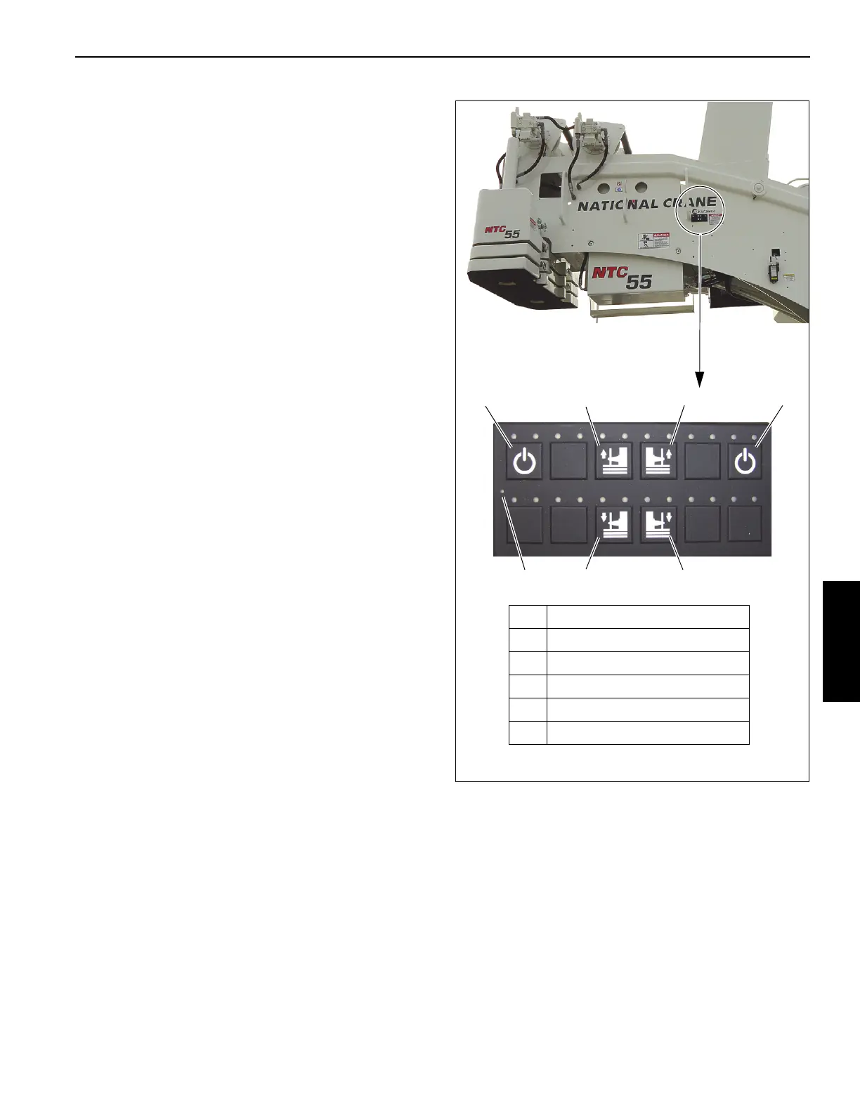
10. Using Counterweight Switch Panel, fully raise
Counterweight Removal Cylinders by doing the
following:
a. Press and hold a Power Button.
b. Press and hold the left and right Counterweight
Removal Cylinder Raise Buttons.
c. Release the left and right Counterweight Removal
Cylinder Raise Buttons when the cylinders are at
the fully raised position.
NOTE: If top counterweight hits wear pads on the
superstructure when raising, swing crane to re-
align counterweight to mounting lugs, lower
counterweight back down onto mounting lugs on
carrier deck to realign counterweight on cylinder
pins, then raise counterweight again.
11. Secure Removable Counterweight to left and right sides
of superstructure using pins (4, Figure 4-12).
NOTE: It may be necessary to jog the cylinders up and
down to install pins.
12. Slightly lower left and right cylinders to relieve the weight
of the counterweight from the cylinder pins.
Stowing the Counterweight
1. Position crane on a firm, level surface.
2. Fully extend and set the outriggers, then level the crane
(see Setting the Outriggers, page 4-2).
3. Set display in Operator’s Console to the
RCL Operating
Mode Screen (Figure 4-11) (see
Section 7, Rated
Capacity Limiter
).
4. While watching the display, rotate superstructure until
Counterweight Removal Slew Position Indicator (yellow
arrows) (1, Figure 4-11) appears in the display, which
indicates the rear of the superstructure is nearly directly
FIGURE 4-13
7868-02
Counterweight Switch Panel
1 Power Buttons
2 Right Cylinder Raise Button
3 Left Cylinder Raise Button
4 Right Cylinder Lower Button
5 Left Cylinder Lower Button
6 Panel Power Indicator (LED)
12
4
31
56
8801

 Loading...


