NATIONAL CRANE Published 9-26-2018 Control # 646-02 4-3
NTC55 OPERATOR MANUAL SET-UP
NOTE: The RCL will automatically preselect the outrigger
position based on inputs from the four outrigger
beam extension monitoring sensors.
5. Remove the front outrigger floats from the carrying
brackets and place the floats under the stabilizer.
6. Secure the front outrigger floats to the stabilizers with
the pins and clips.
7. Select the desired stabilizer with the stabilizer selector
switch and press the extend switch to extend the
stabilizer.
8. Extend all four stabilizers until the truck tires are about
four inches off the ground.
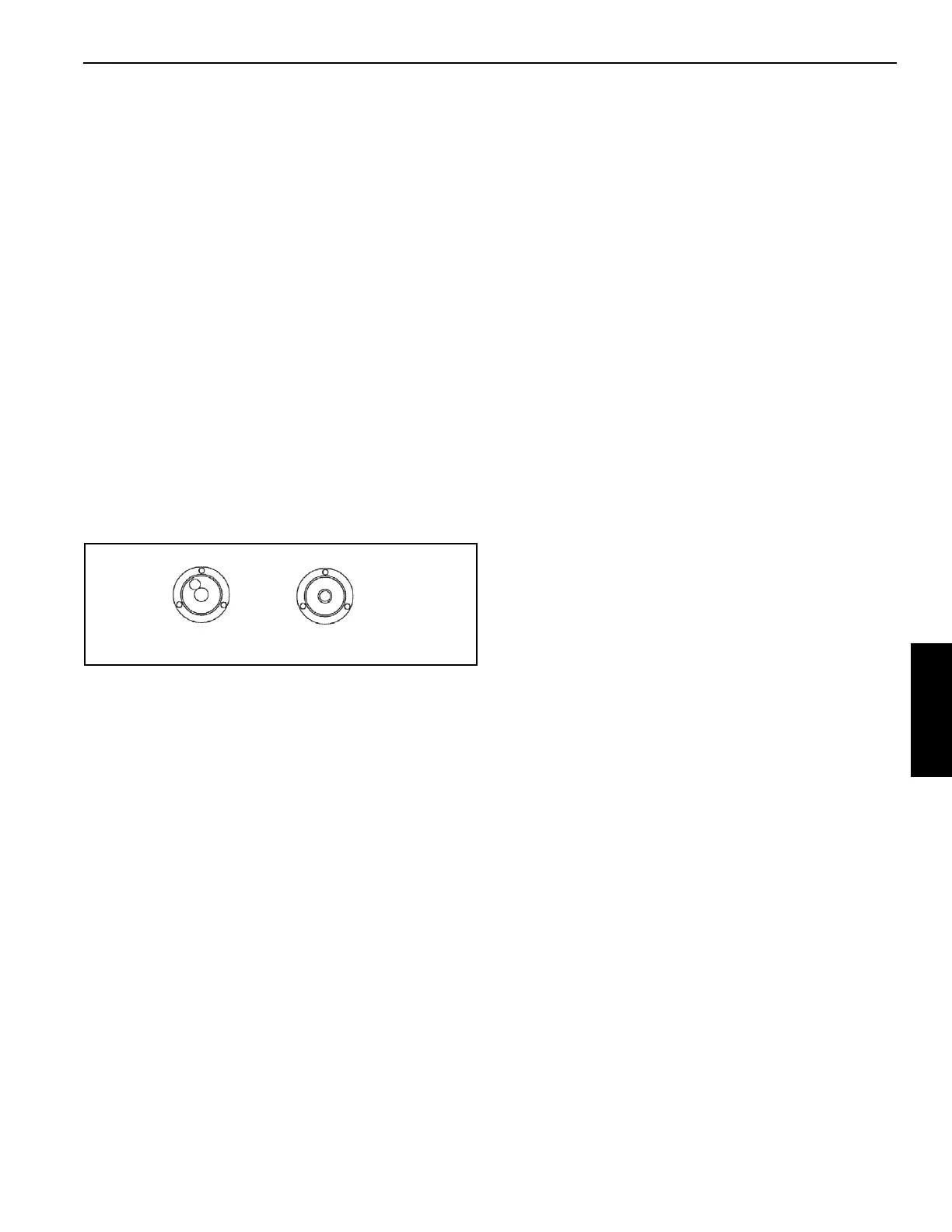
9. Adjust the stabilizers until the bubble in the level
indicator is in the center of the bulls eye. Do not allow the
tires to touch the ground.
10. Using the level indicator, adjust the stabilizers until the
bubble is in the center of the bulls eye. Do not allow the
tires to touch the ground. If it is suspected that the
bubble level indicator is out of adjustment, verify and
adjust the bubble level using the procedures under
Bubble Level Adjustment, page 4-1.
11. Lower the single front outrigger (optional) only after all
other stabilizers are set. Press the front stabilizer switch
to activate and the extend/retract switch to extend. Hold
the extend/retract switch for two seconds after the
stabilizer contacts the ground. The front stabilizer is
automatically set at the correct ground pressure.
12. Verify that the RCL has preselected the outrigger
position mode correctly.
JIB SAFETY INFORMATION
1. Ensure the proper jib mode is selected in the RCL.
2. The anti-two block (A2B) switch weight and cord must
be attached to the jib when deployed.
3. Do not lift the load with the main boom when the jib is
pinned on the tip of the main boom.
4. Operate with jib by radius when main boom is fully
extended. If necessary, increase boom angle to maintain
loaded radius.
When radius is between points listed on capacity chart,
the load shown at the next longer radius shall be used.
5. Operate with jib by boom angle when main boom is not
fully extended. Do not exceed rated jib capacities at any
reduced boom lengths.
When angle is between points listed on capacity chart,
the load shown at next lower boom angle shall be used.
6. Ensure jib is stowed correctly (Figure 4-3):
a. Removal of right side attachment pins (6), without
proper installation of stow pin (1) and jib swing pin
(5), may allow jib to fall off.
b. Extending boom with jib stowed and failure to
remove right side attachment pins (6), will damage
unit upon extension.
7. Only swing jib into working or stowed position when
boom is horizontal, stow pin (1, Figure 4-3) and jib swing
pin (5) are removed and right side attachment pins (6)
are in place. Jib could swing uncontrollably if boom is not
horizontal.
8. Crane shall be fully set up according to proper set-up
procedures outlined previously when stowing or
unstowing jib.
9. Operate boom and turn functions very slowly and
carefully when using jib since extension can increase
boom length by 50%.
10. The area where jib swings around must be clear of
obstructions, personnel and power lines when stowing
and unstowing jib.
11. Use safety glasses when installing pins with hammer.
12. Do not extend/retract boom unless boom is horizontal
when stow pin (1, Figure 4-3) and jib swing pin (5) are
removed during stowing or unstowing procedures.
13. Always put spring clips in pins to ensure that they will
stay in place.
14. When the jib is stowed, the boom can not be fully
retracted if a boom tip attachment option is installed.
Also, on manually extendable jib options:
1. Jib retaining pin (9, Figure 4-3) must always be installed
when operating.
2. All swing around (stow and unstowing) operations shall
be done with jib retracted and pinned.
3. Extendable section may slide out of 1
st
section jib when
jib retaining pin (9, Figure 4-3) is removed. Keep
personnel clear of area.

 Loading...


