NTC55 OPERATOR MANUAL CONTROLS AND OPERATING PROCEDURES
National Crane Published 9-26-2018 Control # 646-02 3-13
The crane controls are located in the crane cab and are used
for all crane functions. See (Figure 3-4 & Figure 3-5) for
crane cab item number (#) identification. For best control
response, run the engine at governed RPM when operating
the crane.
NOTE: The operator must be in the crane cab seat with left
armrest lowered and crane power switch ON for
the crane controls to operate.
Swing Brake Pedal
The swing brake pedal (2, Figure 3-4) is located on the left
side of the crane cab floor. Pressing the pedal down applies
brake to the turret and prevents rotation; releasing the pedal
allows the turret to rotate freely.
Swing Lock Pedal (Optional)
The swing brake pedal (40, Figure 3-4) is located on the left
side of the crane cab floor. The brake pedal is used to
mechanically lock the turret in a given position (360° lock).
Swing Brake Indicator
When the swing brake is locked, the swing brake indicator
(7, Figure 3-3) icon will be displayed on the crane cab
console display panel.
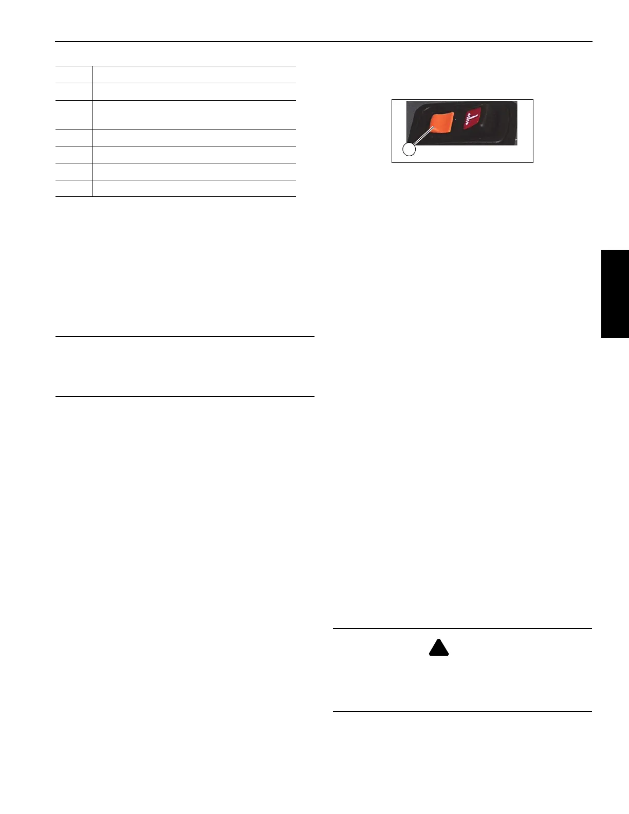
Swing Brake Control Switch
The swing brake control switch (32, Figure 3-5) is located on
the left seat armrest and is a two position switch, press
forward to lock the swing brake. When the swing brake is
locked, the swing brake indicator (7, Figure 3-3) icon will be
displayed on the crane cab console display panel. Press and
slide the back half of the switch (1, Figure 3-6) to unlock the
swing brake.
The back half of the switch (1, Figure 3-6) is designed with a
locking mechanism to secure the swing brake in the locked
position and prevent accidental movement of the cab &
superstructure.
Swing Horn Button
The swing horn button (33, Figure 3-5) is located on the cab
seat left joystick. This horn is used by the operator to provide
a warning that the superstructure is rotating.
Boom Telescope Pedal (Standard with Aux
Hoist)
The crane is equipped with the boom telescope pedal only
when the auxiliary hoist option is included. The telescope
foot pedal (3, Figure 3-4) is located on the crane cab floor
and is used to extend and retract the boom. Pushing down at
the top of the pedal extends the boom out; pushing down at
the bottom of the pedal telescopes the boom in.
Foot Throttle Pedal
The foot throttle (4, Figure 3-4) is located on the crane cab
floor and is used to control the engine speed. Depress the
foot throttle to accelerate the engine speed and release to
return to idle.
Display Panel
The display panel (5 Figure 3-4) is for the Rated Capacity
Limiter (RCL), see operating instructions and screen
displays in this manual.
The RCL provides the crane operator with the information
required for the crane to perform safely within its design
parameters. The RCL displays information on length and
angle of boom, working radius, rated load, total weight being
lifted and outrigger position.
The RCL continuously monitors these parameters and
provides the operator with an updated readout of the crane
status. If a rated capacity condition is approached, the RCL
warns the operator with an alarm and locks out the crane
functions.
36 Single Axis Controller- Main Hoist Lever
37
Single Axis Controller-Boom Telescope/
Auxiliary Hoist Lever
38 Single Axis Controller-Swing Control Lever
39 Seat (only) Slide Adjustment Lever
40 360° Swing Lock Pedal (Optional)
41 Cab Tilt Switch
CAUTION
Do not actuate the Swing Control Lever while the Swing
Brake is engaged, as the turret may push through the
brake. Damage to the swing brake can occur.
Item Description
DANGER
The RCL only aids the operator when properly
programmed with the proper load chart and crane
configuration. To prevent injury or death to personnel, be
sure the RCL is programmed before crane operation.

 Loading...


