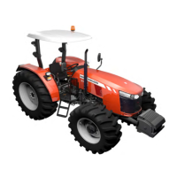
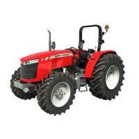
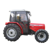
Operation
48
410/420/430 - 001 8903 U1
UZEL
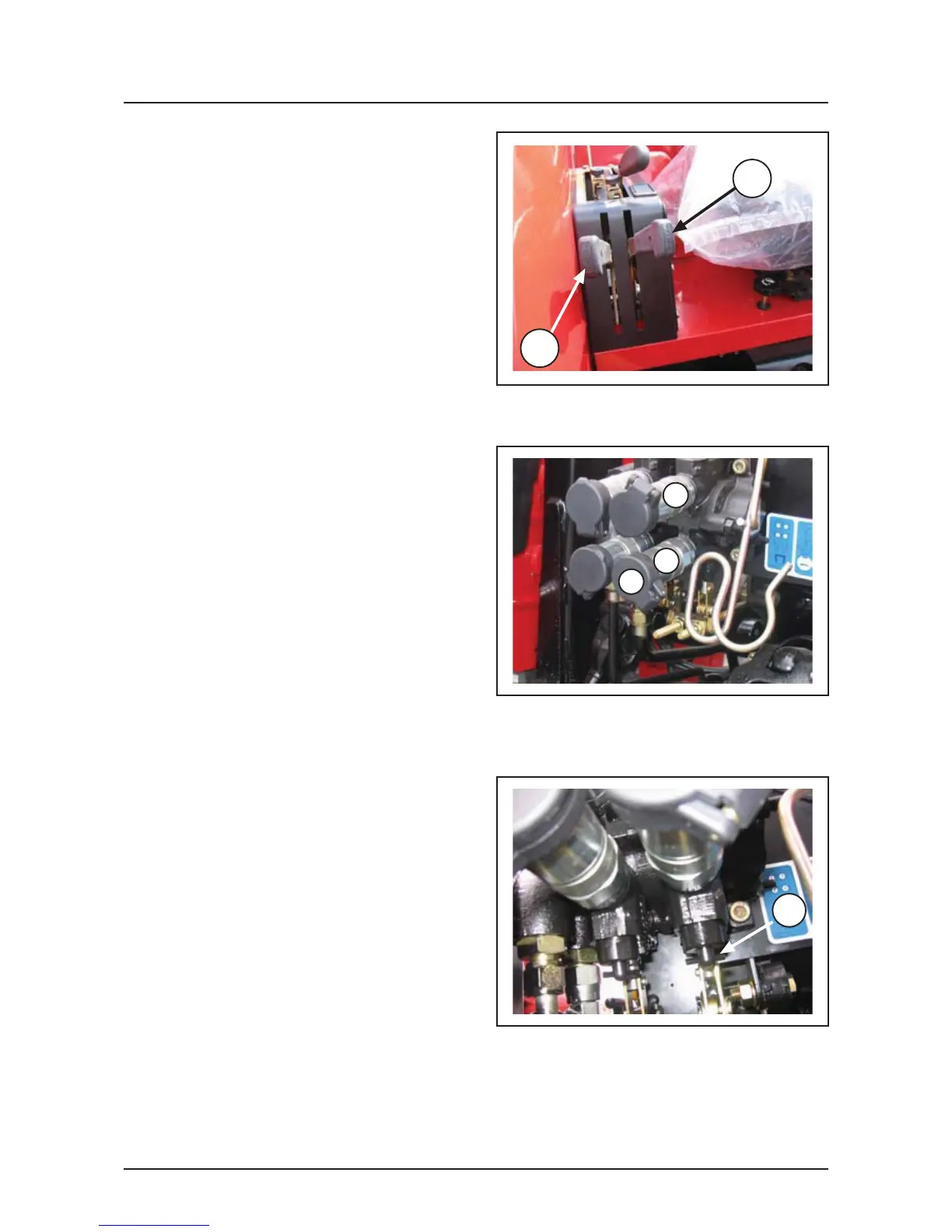
Auxiliary control valve (if fitted)
The control valves and levers are located on the
right-hand side of the seat (Fig. 64). The levers (1,
2) operate the control valves on the rear of the tractor.
Each valve has a control spindle for the selection of
single- or double-acting operation.
It is used on equipment requiring the use of hydraulic
controls using single- or double-acting hydraulic rams
and low input hydraulic motors.
Hydraulic self-sealing, quick-release, couplers are
situated at the rear of the tractor (Fig. 65). Hydraulic
hoses can be coupled or uncoupled, without any loss
of oil. A decal is positioned near the quick-release
couplers which shows the numbered connectors
which correspond to the control lever movements.
Before attaching the hoses be sure that the quick-
release couplers and hose ends are clean and free
from dirt.
To connect, push the implement hose connector into
the quick-release coupler. To disconnect, with the
engine stopped, relieve any pressure by operating
the control levers through their entire range at least
twice. Push the coupler slightly into the connector
and then pull out quickly. The couplers will
automatically uncouple and seal, preventing any loss
of oil. After disconnecting, put protective covers (4,
Fig. 65) on all hose connectors to prevent dirt getting
in.
NOTE: If the implement accidently becomes
disconnected from the tractor the hoses will
automatically uncouple, preventing damage to the
hoses.
Auxiliary hydraulic control valve sections
The tractor is normally fitted with two spring return
valve section, they are spring loaded so they
automatically return to the neutral position when
released.
Each valve section, (Fig. 66) has a control spindle
(3) at the base of the section for the selection of
single- or double-acting cylinders. Screw IN for
double acting cylinders, screw OUT for single acting
cylinders.
Operation - single-acting rams
To operate single-acting rams, screw the control
spindle (3,Fig. 66) fully out, and use only the coupler
marked(1, Fig. 65). Ensure that the implement hoses
are correctly connected to the tractor couplers. Refer
to the appropriate implement Operator Instruction
Book.
To extend the ram, pull the lever back. To retract the
ram, push the lever forwards.
Operation - double-acting rams
To operate double-acting rams, screw the control
spindle (3,Fig. 66) fully in, and attach the hose from
the side of the ram which causes it to extend, to the
coupler marked (1, Fig. 65) and the return hose to
the coupler marked (2). To extend the ram, pull the
lever back. To retract the ram, push the lever forwards.
Fig. 64
Fig. 65
1
2
Fig. 66
2
1
3
4
 Loading...