Operation
50
410/420/430 - 001 8903 U1
UZEL
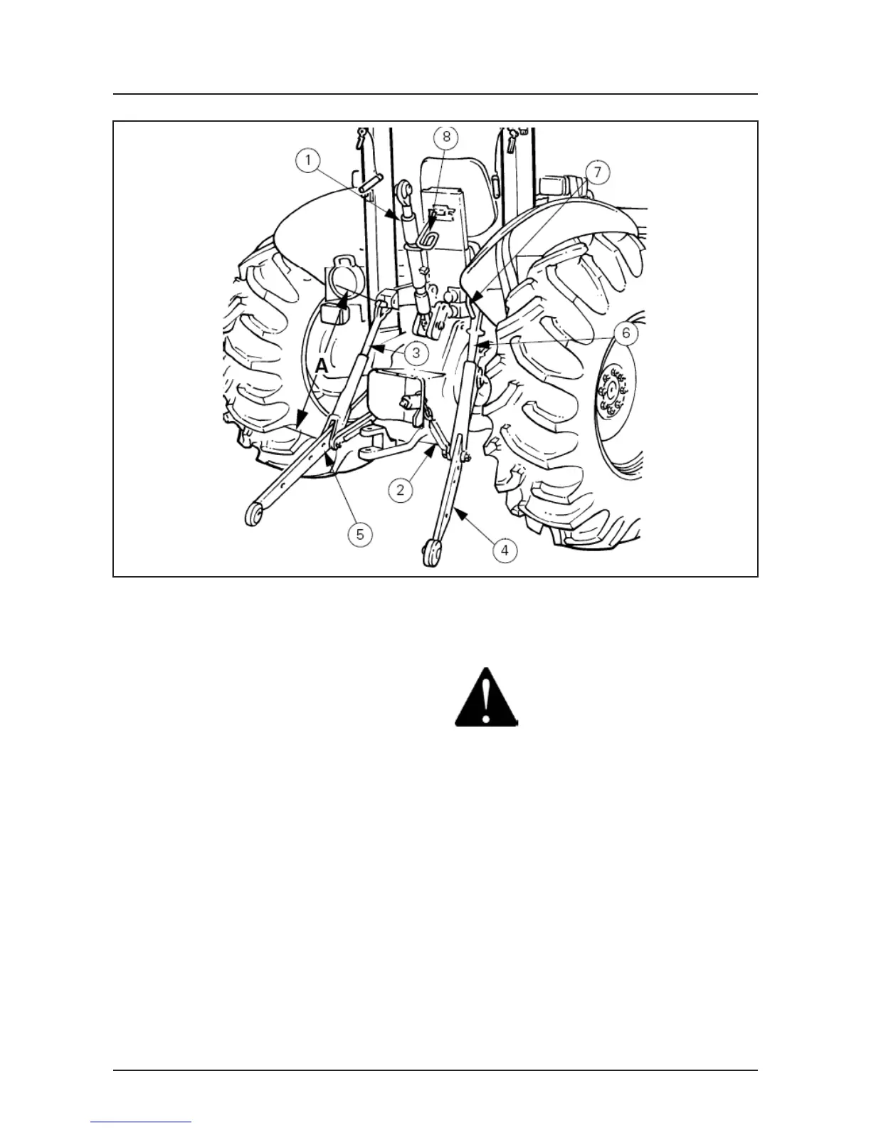
Fig. 66
Lifting linkage
The lower links, (4,Fig. 66) absorb most of the load
exerted by a mounted, or semi-mounted implement.
The links are raised and lowered by the action of the
lift arms.The lift arms are connected to the lift rods
(3) and (6) which couple the lift arms to the lower
links (4). The lower links are ball jointed to allow the
implement to float sideways slightly when operating,
but excessive sideplay which would allow the
implement to contact the rear tires is prevented by
the lower link stabizers (2).
The right-hand lift rod (6) can be adjusted for length
to facilitate the fitting of implements, or leveling the
implement to allow the tractor to work at a different
angle in relation to the ground. The leveling lever (7)
is used to screw or unscrew the upper and lower
components of the lift rod to adjust the length.
Key to Fig. 66:
1. Top link.
2. Stabilizer.
3. Left-hand lift rod.
4. Lower links.
5. Alternative lower link position.
6. Adjustable lift rod.
7. Levelling lever.
8. Top link stowage hook.
Top link
WARNING: DO NOT, in any
circumstances, attempt to pull or tow
from the top link connection. DO NOT
operate the tractor with the threads showing.
The top link, (1,Fig. 66) length is adjusted by turning
the sleeve. The latch must be pulled back before the
sleeve can be turned. The top link is adjusted when
the implement is fitted to give the correct operating
angle. When transporting the tractor, hook the link
into the raised position using the stowage hook.
Lift rod length
The lift rod, (3) must be set to the correct length to
obtain the optimum implement depth and maximum
transport height. The left-hand lift rod length
(dimension 'A' ) is set at the factory to 573 mm (22.56
in). For normal lift height, fit the linkage as shown in
(Fig.66). If an implement is fitted which requires a
higher lift capacity, the lift rods can be relocated in
an alternative hole, (5). This latter position reduces
the operating arc of the lower link end.
NOTE: The lift rod bolts must always be adjusted so
that they can rotate. The bolts must also be through
the corresponding holes in both lower link arms.
 Loading...