17
CHAPTER 8: TROUBLESHOOTING
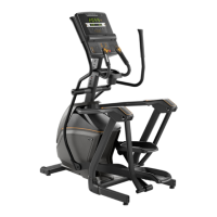
8.2 A5x(EP72) LCB3 LED PLACE AND DEFINITION
+12 - LCB Power indicator light
DN1 - Indicates if the upper console is commanding Elevation 1 DOWN.
DN2 - Indicates if the upper console is commanding Elevation 2 DOWN.
UP1 - Indicates if the upper console is commanding Elevation 1 UP.
UP2 - Indicates if the upper console is commanding Elevation 2 UP.
RPM - Rotation rate for speed.
BRK - Resistance indicator light.
RL - Relay indicator light.
STATUS - Digital communication state indicator light.
OL1 - Elevation 1 error indicator light.
OL2 - Elevation 2 error indicator light.
8.3 SOFTWARE SETTINGS
Unit does not record distance or RPM
If unit resets after 30 seconds despite pedaling verify “incline reset” is ON
in manager mode (P12). Perform console LED segment test to verify console
can display RPM (service 1 in engineering mode) Select another program and
begin pedaling. Look for RPM in lower display If no RPM displays Remove RH
disk (refer to 9.1) Green LED labeled “RPM” on lower control board should
flash when main drive pulley is turned (image x)
If the speed and distance seem low, verify that there are 4 magnets on the
secondary pulley.
If LED does not flash, verify sensor cable is plugged in to lower control board
(image 0093) If sensor cable is plugged in to board, the remove sensor and
perform continuity check. Replace sensor if required. Verify gap between
sensor and drive pulley. If a - e have been performed and RPM does not
display on console, replace lower control board
8.4 CONSOLE/SOFTWARE
Unit does not power up:
Verify unit is plugged in and there is power at the outlet – 120v AC 5A. Verify
green LED on power converter “brick” is lit. Verify power switch on e-port
plate is in the on position. If there is power at the power converter and the
switch is in the on position with no power to the unit:
remove e-port plate (refer to image 0096)
check main power switch continuity – image 0417
replace switch if necessary
If steps 1-3 are all “yes” then:
Remove RH disk (refer to instructions in section 9.1). Check power LED
on lower control board labeled RL. If LED is not lit, check for power at lower
control board power cable. Replace cable if necessary. Check that console
communication cable is plugged into board.
If #4 is “yes” then:
Remove console
Unplug RJ45 console communication cable (refer to section 9.9).
On RJ45 plug, measure voltage at white and blue wires. The measurement
should be 12v. Replace console communication cable if necessary.
If #5 is yes, then replace upper console control board.
Plug in unit and check for power.
RPMRBK
DN1
DN2
UP1
UP2
+12
OL1ST ATUSOL2 RL
 Loading...