57
CHAPTER 11: UPGRADES
11.4 INSTALLING ADJUSTABLE TENSIONER
1. To replace belt tensioner with an adjustable bracket assembly.
REWORK PARTS REQ
1. Part # 0000089133 (short - this is used on most units) or 0000089456
(long) - Replacement Tensioner Kit: contains tensioner assembly, zip ties,
and shims.
2. Part # 0000089129 - Adjustment Block. Send one per technician (can
be reused on multiple units).
TOOLS AND EQUIPMENT REQUIRED
1. 24 mm Socket / Ratchet.
2. Matrix Wheel Puller.
3. Torque Wrench to 2000kgf*cm/196 N-m (145 ft*lbf).
4. #2 Phillips Head Screwdriver.
5. 5 mm, 6 mm, and 8 mm Allen / Hex.
6. 13 mm / 17 mm Open End Wrench.
7. Pliers.
8. Side Cutter.
PROCEDURE
1. Read these directions all the way through before proceeding.
2. Follow procedure as outlined in Section 9..1 of the Ascent Trainer
Service Manual to remove the right side disc from the machine.
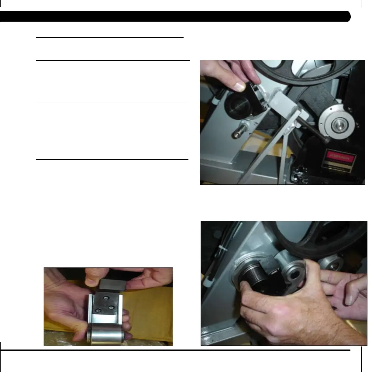
3. Loosen the belt tension lock nut with 17mm wrench, and back off the
screw so that the drive belt can be removed from the unit. (see section
9.4 of the Ascent Trainer Service Manual). Remove the locking nut to
allow more room to fit the parts in later steps.
4. Use a 5 mm Allen wrench to remove the tensioner from the machine.
*Note that several of the Phillips screws will need to be removed so the
plastic covers can be spread far enough to remove tensioner completely
from mounting post.
5. If required, remove the non-crowned tension roller from the old
assembly and move it to the new assembly. Rollers that have a crowned
face or rollers consisting of two bare ball bearings are to be replaced with
the new roller kit.
6. Check the 5 screws on the tensioner assembly. They should be only
lightly finger tight and the three pieces should all slide freely against
each other without excessive slop.
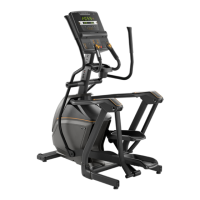
7. Place the alignment block over the small pulley and then place the
new tensioner onto the frame.
8. Apply pressure across the small pulley and the roller to bring the two
parts into contact with the alignment block.
 Loading...