25
6.13 TENSION SET REPLACEMENT
1) Remove the front shrouds as outlined in Section 6.1.
2) Remove the middle shrouds as outlined in Section 6.2.
3) Remove the console as outlined in Section 6.3.
4) Remove the handlebar from the rope as outlined in Section 6.4.
5) Remove the rubber center cover as outlined in Section 6.5.
6) Remove the plastic center cover as outlined in Section 6.6.
7) Remove the rubber ball from the end of the rope.
8) Allow the rope to coil around the rope axle set.
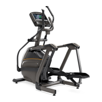
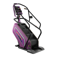
9) Remove the eye bolts that apply tension to the belt (Figures A & B).
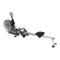
10) Remove the 2 screws holding the speed sensor to the frame (Figure C).
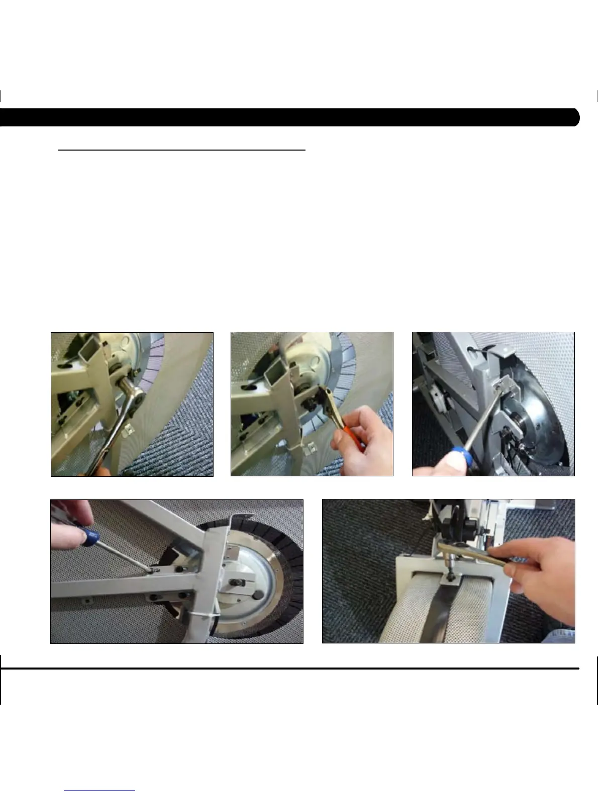
11) Remove the 4 screws holding the magnet set to the frame (Figure D).
12) Remove the 4 screws holding the wheel cover to the frame (Figures E & F), this will allow you to roll the wheel covers / center axle from the frame
(Figure G) and remove the magnet set (Figure H).
13) Disconnect the tension wiring from the magnet set (Figure I).
14) Remove the screw holding the tension knob to the frame and remove the tension set (Figures J & K).
15) Reverse Steps 1-14 to install a new tension set.
16) Test the rower for function as outlined in Section 6.19.
FIGURE A
FIGURE B
FIGURE C
FIGURE D
FIGURE E
CHAPTER 6: PART REPLACEMENT GUIDE
 Loading...