7
CHAPTER 2
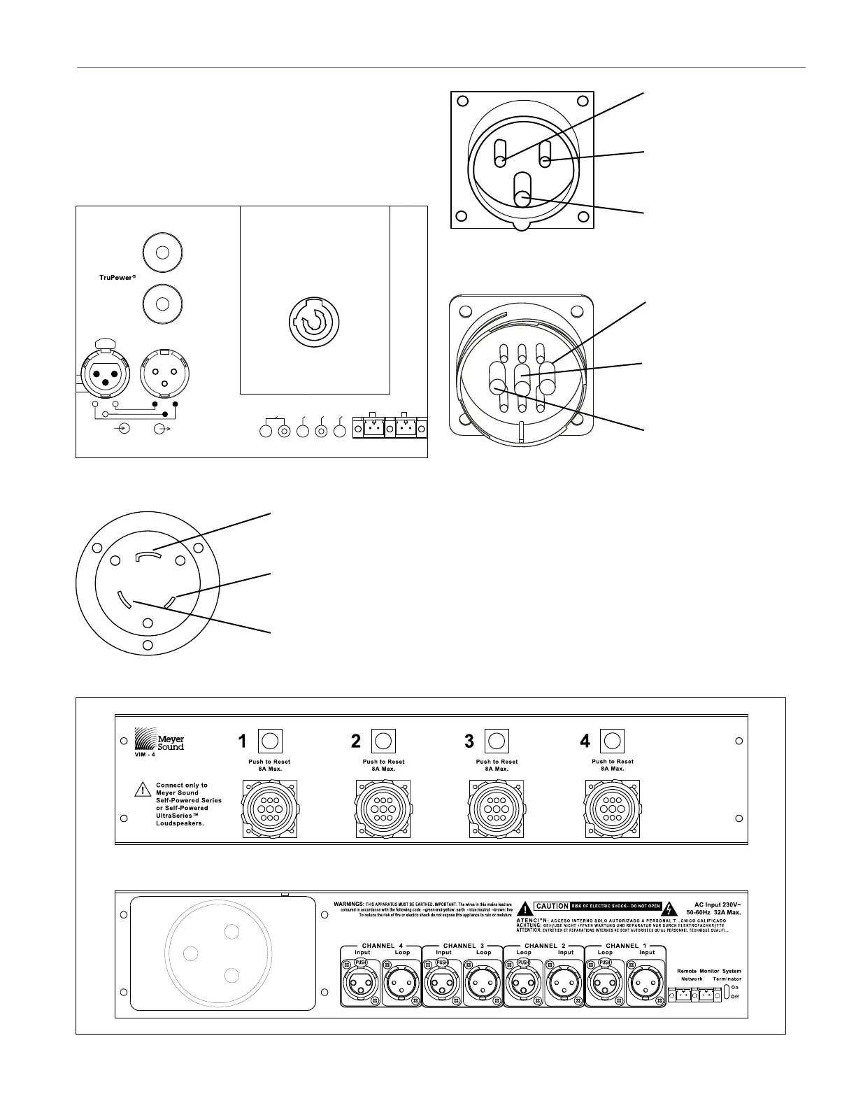
POWER CONNECTOR WIRING CONVENTIONS
The MICA loudspeaker requires a grounded outlet. It is very
important that the system be properly grounded in order to
operate safely and properly. Figures 2.2, 2.3, 2.4 and 2.5
illustrate correct wiring for the creation of power cables and
distribution systems.
Acti ve
Low Ch Limit
High C h Li mit
MICA
2 +
Earth / Chassis
1
Case
220K �
ESD
3 -
10K
�
Balanced
1
2
3
1
3
2
Loop
Input
Netwo rk
S
e
rv
i
c
e
W
i
n
k
R
e
s
e
t
A
c
t
i
v
i
t
y
Rem ote Mon itor System
PUSH
Figure 2.2. MICA rear user panel with PowerCon connector
ground (green/yellow)
Y-line (brown)
X-neutral (blue)
Figure 2.3. L6-20 power connector pin-out
neutral (blue)
line (brown)
ground (green/yellow)
Figure 2.4. IEC 309 power connector pin-out
line (brown)
ground (green/yellow)
neutral (blue)
Figure 2.5. VEAM multi-pin connector power pin-out
If the loudspeaker is fitted with the VEAM multipin
connector, see the Meyer Sound document VEAM Cable
Wiring Reference (PN 06.033.113) for wiring conventions
and pin-outs for AC, audio, and RMS connections.
Meyer Sound offers the VIM-4 (VEAM interface module) to
distribute power, audio and RMS to MICA loudspeakers
fitted with 4 VEAM connectors in the front and a single-
phase IEC 309 32-amp connector in the rear, as shown
below in Figure 2.6.
Figure 2.6. VIM-4 module, front (top) and rear (bottom)

 Loading...