17
CHAPTER 5
Low-Frequency Design Strategies
While wave-guides provide isolated control over various
mid- to high-frequency coverage areas, the low-frequency
section of a MICA array still requires mutual coupling
— with equal amplitude and phase — to achieve better
directionality.
Low-frequency directionality is less dependent on the array’s
relative splay angles and more dependent on the number of
elements of the array. At low frequencies, the more elements
in the array (the longer the array), the more directional the
array becomes, providing more SPL in this range. The
directional control of the array is achieved when the length
of the array is similar or larger than the wavelength of the
frequencies being reproduced by the array.
Optimizing the Array
Once the design (number and type of elements, vertical
splay angles and horizontal splay angles between arrays)
has been designed using MAPP, you can effectively
optimize the array by driving it with multiple equalization
channels, or zones. Typically arrays are divided in two or
three zones depending the design and size of the array.
To optimize and EQ the array, different strategies are used
for high frequencies (long throws and short throws) and low
frequencies.
High-Frequency Equalization Strategies
For the far field, air absorption plays a critical role. The
longer the distance, the greater the attenuation at high
frequencies. In this zone, high frequencies generally need
a correction to compensate for energy lost over distance;
the correction needed is usually proportional to the distance
and high-frequency air absorption.
In the near- to mid-field, the air absorption is not nearly
as critical; in this zone, high frequencies need little or no
additional correction.
TIP: If your MICA line array uses a third zone
for short throws, high frequencies there may
need to be attenuated to more appropriate near-field
levels.
Low-Frequency Strategies
Although the array can (and usually should) be zoned
for implementing different equalization curves for high
frequencies, similar or identical equalization should be
maintained in all the low-frequency filters. Different low-
frequency equalization settings in the same array will
degrade the desired coupling effect.
For the same reason, severe gain tapering is not
recommended for line arrays, since adjusting various zones
with an overall amplitude control for each results in the
following:
1. The length of the line array column is effectively
shortened
2. Directionality decreases at low frequencies.
3. Low-frequency headroom decreases.
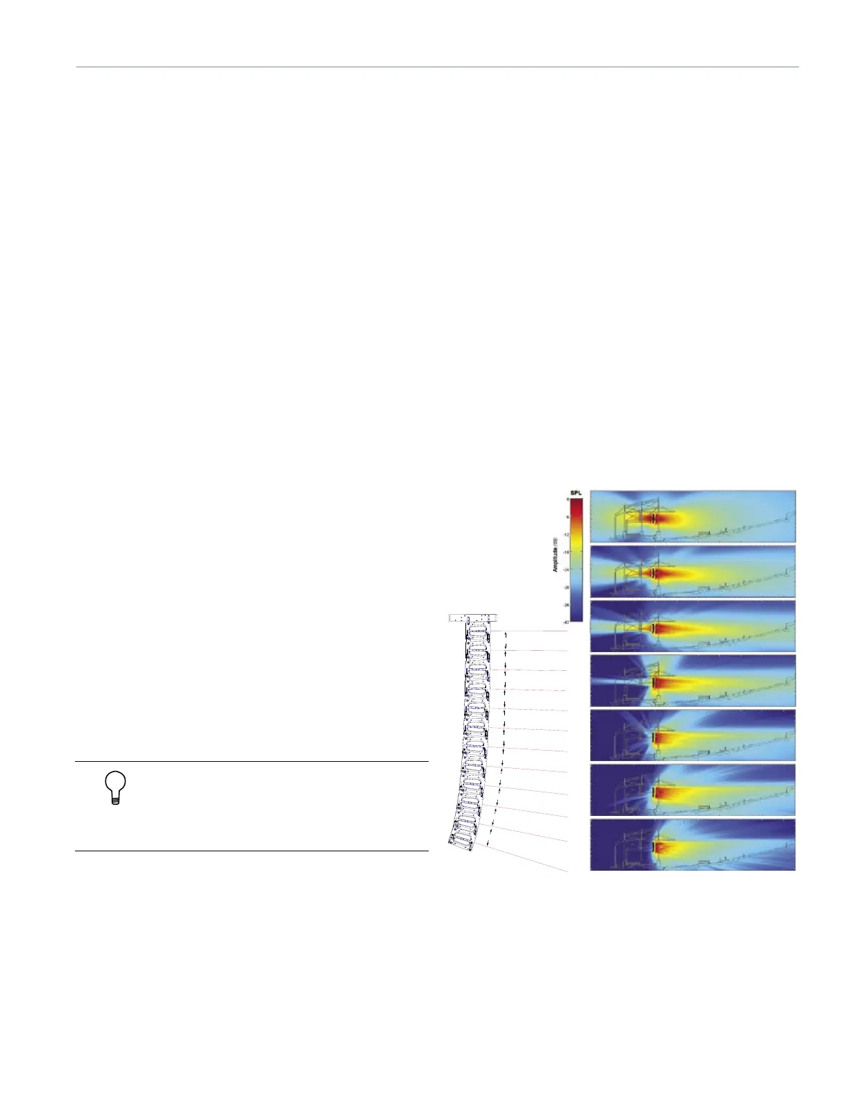
Figure 5.2 shows a series of MAPP Online predictions
based on an example MICA system design. In this case,
small vertical splay angles on the upper part of the array
are used to cover longer distances, while greater angles in
the lower elements to increase vertical coverage for shorter
distances.
Figure 5.2. MAPP Online plots (right) illustrate the vertical directivity
characteristics of the array (left), with a section view of the venue
superimposed.
2 kHz
4 kHz
1 kHz
500 Hz
250 Hz
8 kHz
125 Hz

 Loading...