10
CHAPTER 3
NOTE: Meyer Sound’s Galileo™ loudspeaker
management system and LD-3 compensating
line driver are highly recommended when driving
systems using multiple loudspeakers. These
processors, in addition to maintaining signal integrity
for long cable paths, offer independent outputs and
filters to help you integrate sub-systems and optimize
MICA array performance.
NOTE: For details on MICA’s audio input
characteristics and amplification, see
Appendix B.
AMPLIFICATION AND PROTECTION CIRCUITRY
MICA is powered by the Meyer Sound MPW-4/MICA
amplifier, a high-power four-channel amplifier with a total
power of 3,020 watts (6,000 watts peak). The MPW-4/MICA
amplifier utilizes complementary-power MOSFET output
stages (class AB/H). All the specific functions for the MICA
loudspeaker such as crossover points, frequency and
phase response, and driver protection are determined by
the control card installed inside the MPW-4/MICA amplifier.
NOTE: For details on replacing the MPW-4/
MICA amplifier see Appendix A.
CAUTION: Please note that MICA and other
Meyer Sound loudspeaker amplifiers are
different. Specific functions for each model, such as
crossover points, frequency and phase correction
and driver protection are determined by the control
cards installed inside the amplifier. Do not exchange
amplifiers between MICA and other Meyer Sound
loudspeakers.
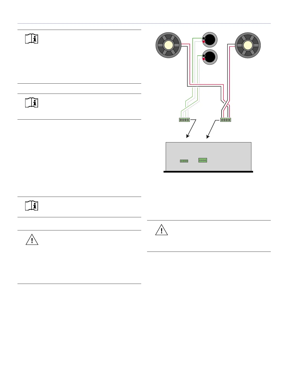
MICA INTERCONNECTIONS
The two 4-ohm, 10-inch, low-frequency cone drivers
are each powered with 950 watts from two channels of
the four-channel MPW-4/MICA amplifier. The two 3-inch
diaphragm, 8-ohm high-frequency compression drivers are
each powered with 560 watts from the other two channels.
Figure 3.2 shows how MICA’s drivers are connected to the
amplifier.
User Panel
W
h
i
t
e
G
r
e
en
W
h
i
t
e
G
r
e
e
n
+
+
-
-
R
e
d
B
l
a
c
k
R
e
d
B
la
c
k
+
-
+
-
Left Front
Right Front
-------- Fans --------
Upper Control Card
24.033.042.46
Lower Control Card
24.033.042.45
MICA
MPW-4 Amplifier Chassis
(Top View)
A
B
Figure 3.2. MICA internal wiring harness diagram
All Meyer Sound loudspeakers are tested and shipped with
the drivers in correct alignment. However, if a driver needs
to be replaced, make sure the replacement is reinstalled
with the correct polarity.
CAUTION: Failure to connect a replacement
driver using the proper polarity will result
in severe degradation in frequency and phase
response and can harm the drivers and amplifier.
CABLING
MICA is available with two different cabling/connection
options. One is the Meyer Sound/VEAM cable system,
which combines AC power, audio signal, and RMS network
data into one heavy-duty cable with a single matching
connector per MICA cabinet.
The other (standard) system uses three separate cables
and connectors per cabinet for the AC line current, signal,
and RMS data. However, the three can be consolidated to
create a “multi-cable” by looming them together for quick
connection to each cabinet. This ensures no patching errors
and a minimum of discrete cables behind the array.
A ring/stud fitting is provided on the rear of the MICA
loudspeaker to act as a strain relief for cabling. Using this
fitting will minimize the chance of cables being damaged
during installation.

 Loading...