11
CHAPTER 3
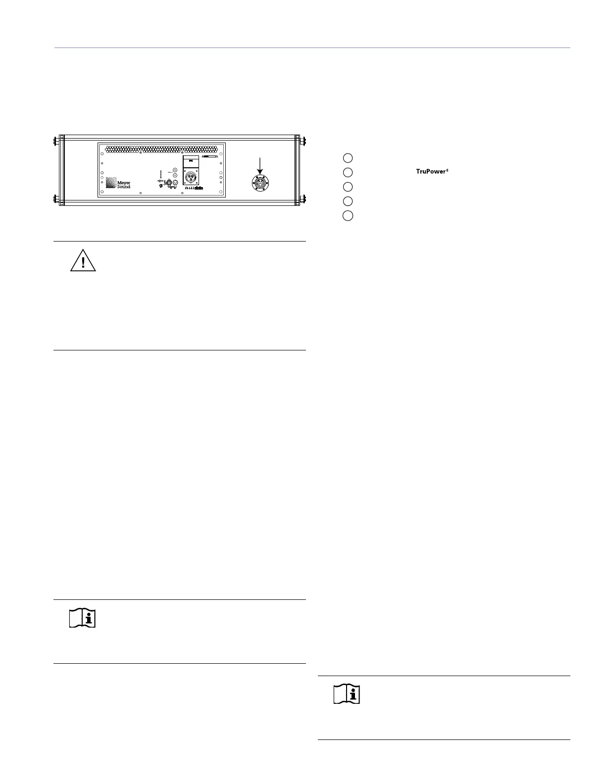
To utilize the strain relief fitting, insert the signal, data,
and AC connections into each loudspeaker as the array is
being rigged (swag all cables under the rain hood’s sides if
installed), and tie the cables off to the ring/stud fitting, as
shown in Figure 3.3.
R
E
-
C
I
R
K
-
I
T
P
U
S
H
R
E
-
C
I
R
K
-
I
T
P
U
S
H
10
10
!
RIS KO FE LEC TRIC S HOCK
DO NOT OPEN
CAU TION
95-125V~
50-60Hz
2000WRMS MAX
OperationalV olta geRang e:
Turnon 85V ~ Turnoff 134V ~
Turnon 165V ~ Turnoff 264V ~
208-235V~
50-60Hz
2000WRMS MAX
Auto-Volta geSelect
ATE NCI ÓN: AC CES O INTE RN O SOL O
AUTO RIZA DO A PER SON AL TÉC NICO C ALIF ICAD O
ACH TUNG: G EHÄUS E NICH TÖ FFNE NW ARTU NG
UND REPAR ATUR NUR DUR CHE LEK TROFAC HKRÄ FTE
ATT ENT ION: E NTR ETI EN ET R EPA RAT IONS
INTE RN ES NE S ONT A UTOR ISE ES Q U'AU
PE RSO NNE L TEC HNIQ UE QUA LIF IÉ
UK WA RNI NG:
THIS APPA RAT US MUS T BE E ART HED .
NOOPERA TORSER VICEABLEP AR TSINSIDE.
REFERSER VICINGT O QUALIFIED PERSONNEL
WAR NING S:
THIS PRO DUCT M UST B E GR OUNDE D.
Thissurface ma yreac hhigh temperatureswhilein use .
Toensure pr operoperation, allo watleast 6inc hes
clearancefr omthissurface andadequateventilation.
Nooperator ser viceab lepar ts inside .
Refer ser vicingtoqualified per sonnel.
Toreduce theriskof fireor electricshoc k
donot expose thisapplianceto rainor moisture .
Act ive
Low Ch Lim it
Hig hC hL imit
MI CA
2+
Earth /Chassis
1
Case
220K Ω
ESD
3-
10K Ω
Balanced
1
2
3
1
3
2
Loop
Input
Netw ork
S
e
r
v
i
c
e
W
i
nk
R
e
s
e
t
A
c
ti
v
i
t
y
Re mote Mon itor S yst em
Me ye r So und , Be rk el ey, C A. US A
PUSH
Cable Tie-Off Point
Figure 3.3. Cables are easily tied off using the rear ring/stud fitting.
CAUTION: The strain relief ring and stud
fitting must be used only to secure system
cabling. This fitting is not intended to be used with
system rigging or a pull-back motor (pulling the
bottom of the array backward to increase downward
tilt). The strain relief fitting is mounted to the side of
the amplifier area so as not to interfere with the rain
hood (if fitted) and the amplifier fan exhaust area.
THE TRUPOWER LIMITING SYSTEM
Conventional limiters assume a constant loudspeaker
impedance and therefore set the limiting threshold by
measuring voltage only. However, this method is inaccurate
because the loudspeaker’s impedance varies throughout
its frequency range, changing in response to the frequency
content of the audio source. In addition, the impedance also
changes due to temperature variations in the voice coil and
magnet. Consequently, conventional limiters begin limiting
prematurely, which under-utilizes system headroom and
lessens the loudspeaker’s dynamic range.
In contrast, TruPower limiting (TPL) accounts for varying
loudspeaker impedance by measuring current as well as
voltage to compute the actual power dissipation in the
voice coil. TPL improves performance before and during
limiting by allowing each driver to produce maximum SPL
across its entire frequency range.
NOTE: TPL only reduces the signal level
to keep the voice coil below its maximum
operating temperature, hence the peaks are
unaffected.
In addition, TPL eliminates power compression when the
system is operated at high levels for extended periods, and
also extends the driver life cycle by controlling voice coil
temperatures.
The actual power is monitored for all four of MICA’s
amplifier channels. When the safe continuous power level is
exceeded, the TPL limiter controlling that amplifier channel
engages. TPL activity is indicated by the LEDs on the user
panel (Figure 3.4).
Active
Low Ch Limit
High Ch Lim it
MICA
2 +
Earth / Chassis
1
Case
220K �
ESD
3 -
10K
�
Balanced
1
2
3
1
3
2
Loop
Input
Network
S
e
r
v
i
c
e
W
i
n
k
R
e
s
e
t
A
c
t
i
v
i
t
y
Remote Monitor System
PUSH
Figure 3.4. MICA Limit LEDs
Low- and Mid-Frequency Limiters
MICA’s left and right 10-inch cone drivers are powered by
separate amplifier channels, each with a power detector
but routed to one limiter; the limiter tracks both channels
and uses the higher of the two values to engage. By limiting
both amplifier channels equally, any anomalies in the
frequency range shared by the drivers are eliminated during
limiting. The Low Ch Limit LED on the user panel indicates
TPL activity for these two drivers. When the power level and
voltage for both low channels returns to normal — below
the limiter’s threshold — the limiter will cease operation.
High-Frequency Limiter
The two 3-inch diaphragm high-frequency compression
drivers are also powered by two amplifier channels
receiving identical audio signals; these channels have both
TPL and peak limiters. The limiter tracks both channels and
uses the higher of the two values to engage. By limiting
both amplifier channels equally, any anomalies in the
frequency range shared by the drivers are eliminated during
limiting.
The High Ch Limit LED is used to indicate any limiting
activity for these drivers. When the LED turns on and off in
rapid succession, it indicates peak limiting; when it turns on
and off slowly, it indicates TPL activity. When engaged, the
peak limiter prevents signal peaks from causing excessive
distortion in the amplifier channel, preserving headroom
and maintaining smooth frequency response at high levels.
When the power level and voltage for both high channels
returns to normal — below the limiter’s threshold — the
limiter will cease operation.
NOTE: The limiting circuitry utilizes optical
limiters that add no noise and have no effect
on the signal when the limiter is not engaged and
the LED is inactive.

 Loading...