27
CHAPTER 7
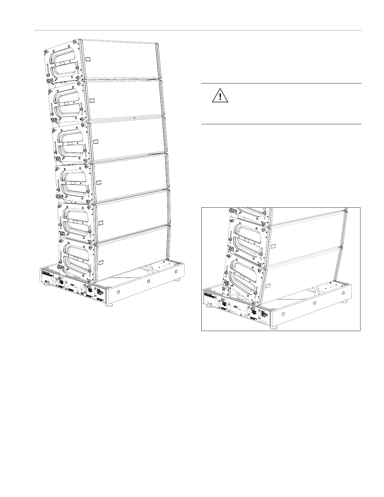
Figure 7.6. Ground-stacking MICA enclosures using the MG-MICA
multipurpose grid
MICA Loudspeaker Pinned Directly to MG-MICA Grid
■ Use the 2.5 position on the rear GuideALink to achieve
a 0-degree orientation with respect to the grid.
■ Use the 0 position to achieve a 2.5-degree downtilt.
■ Use the 6 position to achieve a 3.5-degree uptilt.
MICA Loudspeaker Pinned Directly to 600-HP
Subwoofer
■ Use the 0 position on the rear GuideALink to achieve a
0-degree orientation with respect to the 600-HP.
■ Use the 4 position to achieve a 4-degree uptilt
(positions 5 and 6 cannot be pinned).
■ No downtilt is achievable without the use of the MDTL-
MICA downtilt link (see the following section).
600-HP Subwoofer Pinned Directly to MG-MICA Grid
■ Use the -3 position on the rear GuideALink to achieve a
0.5-degree uptilt with respect to the grid.
■ Use the 0 position to achieve a 2.5-degree downtilt.
CAUTION: Do not use 600-HP rear
GuideALink positions greater than 0 when
ground-stacking. These are for flown applications
only and may make the stack unstable.
The Optional MDTL-MICA Downtilt Link
The MDTL-MICA downtilt link adds a fixed amount of
downtilt to ground-stacked MICA loudspeakers, with an
additional 6 degrees of adjustment possible with the MICA’s
rear GuideALinks. The downtilt link connects between the
MG-MICA grid or the top 600-HP subwoofer and the lowest
MICA loudspeaker.
Figure 7.7. Adding downtilt when ground-stacking with the MDTL-MICA link
MICA Loudspeaker Pinned to Downtilt Link and MG-
MICA Grid
■ Use the 0 position on the rear GuideALink to achieve an
18.5-degree downtilt with respect to the grid.
■ Use the 6 position to achieve a 12.5-degree downtilt.

 Loading...