31
APPENDIX A
REMOVING THE MPW-4/MICA AMPLIFIER
If you need to remove the MPW-4/MICA amplifier from a
MICA loudspeaker, perform the following steps:
1. Using a #2 Phillips screwdriver, remove all six screws
from the amplifier module — three each on the left and
right sides. This will free the MPW-4/MICA electronics
module from MICA cabinet (Figure A.1).
R
E
-
C
I
R
K
-
I
T
P
U
S
H
R
E
-
C
I
R
K
-
I
T
P
U
S
H
10
10
!
RIS K OF ELE CTR ICS HOCK
DO NOT OPE N
CA UT IO N
95-125V
~
50-60Hz
2000WRMS MAX
OperationalV olta geRang e:
Turnon 85V
~
T urnoff134V
~
Turnon 165V
~
Turn off264V
~
208-235V
~
50-60Hz
2000WRMS MAX
Auto-Volta geSelect
AT E NC IÓN
: AC CE SO IN TER NO SO LO
AUTO RIZ ADO A PE RS ONA L TÉ CNIC O CA LIFI CADO
AC HT UN G
: GEH ÄUSE NI CHT ÖFF NEN WAR TUNG
UND REP AR ATUR NUR DUR CH ELEK TROF ACHK RÄF TE
AT T E NT IO N
: EN TRE TIE N ET R EP ARA TI ON S
INT ER NES N E SON T AUTO RIS EE S QU'A U
PE RS ONNE L TE CHN IQU E QUA LI FIÉ
UK WA RN IN G
:
TH IS AP PA RA TUS MU ST B E E AR THE D.
NOOPERA TOR SER VICEABLE P AR TSINSIDE.
REFERSER VICING T O QUALIFIED PERSONNEL
WA R NI NG S :
TH IS PR ODUC T MUS T BE GR OUN DED.
Thissurface ma y reach hightemperatures whileinuse .
Toensure pr oper operation, allo wat least6inc hes
clearance fr omthis surfaceandadequate ventilation.
Nooperator ser viceab le par tsinside .
Ref erser vicing toqualifiedper sonnel.
Toreduce therisk offireor electricshoc k
donot e xposethisappliance torain ormoisture .
Ac tive
Lo wC hL imi t
Hi gh Ch Li mit
MI C A
2+
Ear th/Chassis
1
Case
220K
Ω
ESD
3-
10K
Ω
Balanced
1
2
3
1
3
2
Loop
Input
Ne twork
S
e
r
v
i
c
e
W
i
n
k
R
e
s
e
t
A
c
t
i
v
i
t
y
R em ot e Mo ni to r S ys tem
Meye r Sou nd, Berk eley, C A. US A
PUSH
R
E
-
C
I
R
K
-
I
T
P
U
S
H
R
E
-
C
I
R
K
-
I
T
P
U
S
H
10
10
!
RIS K OF ELE CTR ICS HOCK
DO NOT OPE N
CA UT IO N
95-125V
~
50-60Hz
2000WRMS MAX
OperationalV olta geRang e:
Turnon 85V
~
T urnoff134V
~
Turnon 165V
~
Turn off264V
~
208-235V
~
50-60Hz
2000WRMS MAX
Auto-Volta geSelect
AT E NC IÓN
:
AC CES O INT ERN O SOL O
AUTO RIZ ADO A PE RS ONA L TÉ CNIC O CA LIFI CADO
AC HT UN G
:
GE HÄUS E NIC HT ÖFFN EN WART UNG
UND REP AR ATUR NUR DUR CH ELEK TROF ACHK RÄF TE
AT T E NT IO N
:
EN TRE TIE N ET R EPA RA TION S
INT ER NES N E SON T AUTO RIS EE S QU'A U
PE RS ONNE L TE CHN IQU E QUA LI FIÉ
UK WA RN IN G
:
TH IS AP PA RA TUS MU ST B E E AR THE D.
NOOPERA TOR SER VICEABLE P AR TSINSIDE.
REFERSER VICING T O QUALIFIED PERSONNEL
WA R NI NG S :
TH IS PR ODUC T MUS T BE GR OUN DED.
Thissurface ma y reach hightemperatures whileinuse .
Toensure pr oper operation, allo wat least6inc hes
clearance fr omthis surfaceandadequate ventilation.
Nooperator ser viceab le par tsinside .
Ref erser vicing toqualifiedper sonnel.
Toreduce therisk offireor electricshoc k
donot e xposethisappliance torain ormoisture .
Ac tive
Lo wC hL imi t
Hi gh Ch Li mit
MI C A
2+
Ear th/Chassis
1
Case
220K
Ω
ESD
3-
10K
Ω
Balanced
1
2
3
1
3
2
Loop
Input
Ne twork
S
e
r
v
i
c
e
W
i
n
k
R
e
s
e
t
A
c
t
i
v
i
t
y
R em ot e Mo ni to r S ys tem
Meye r Sou nd, Berk eley, C A. US A
PUSH
S
c
r
e
w
L
o
c
a
t
i
o
n
s
S
c
r
ew
L
o
ca
t
i
o
ns
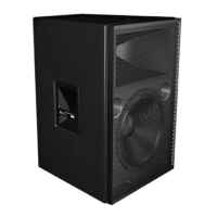
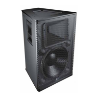
Figure A.1. Location of the six screws securing the MPW-4/MICA
amplifier module
2. Carefully slide the amplifier module out of the cabinet
using care not to stress the cables.
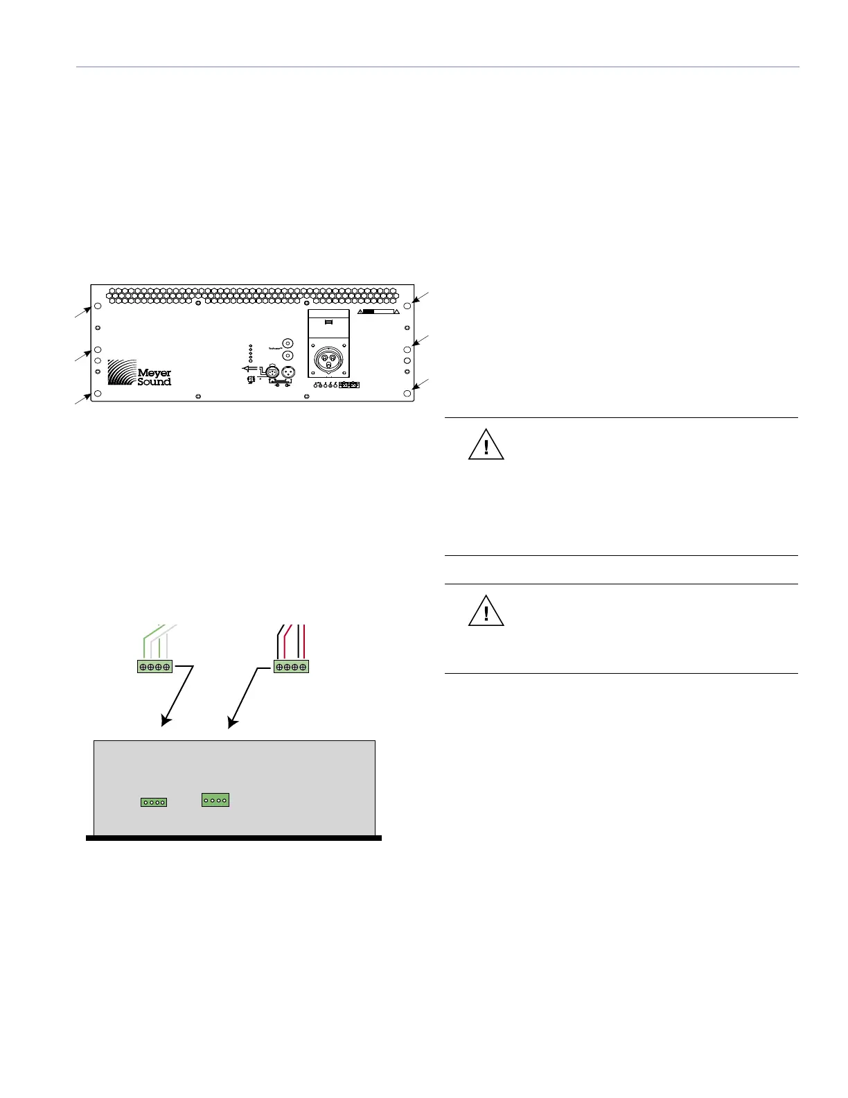
3. Disconnect the two 4-pin loudspeaker connectors. Note
that the harness with red and black wires goes to the
connector closest to the center of the amplifier module,
and labeled “A”, while the harness with green and white
cables goes to the connector closest to the left side,
and labeled “B” (Figure A.2).
User Panel
W
h
i
t
e
G
r
e
en
W
h
it
e
G
r
ee
n
+
+
-
-
R
e
d
B
l
ac
k
R
e
d
B
l
a
c
k
+
-
+
-
Left Front
Right Front
-------- Fans --------
Upper Control Card
24.033.042.46
Lower Control Card
24.033.042.45
MICA
MPW-4 Amplifier Chassis
(Top View)
A
B
Figure A.2. MICA’s two 4-pin connectors
REPLACING THE MPW-4/MICA AMPLIFIER
To replace MICA’s MPW-4 amplifier, do the following:
1. Gently slide the amplifier partially back into MICA and
connect the two loudspeaker connectors. Make sure
they are connected properly. The harness with red
and black wires goes to the connector closest to the
center of the amplifier module, and labeled “A”, while
the harness with green and white cables goes to the
connector closest to the left side, and labeled “B”.
2. Slide the amplifier module the rest of the way into the
cabinet, until it rests against the foam gasket. Start all
six screws into the holes before tightening them.
3. Once all six screws are started, tighten them using a #2
Phillips screwdriver.
CAUTION: Please note that MICA and other
Meyer Sound amplifiers are different. Specific
functions for each model, such as crossover
points, frequency and phase correction and driver
protection are determined by the control cards
installed inside the amplifier. Do not exchange
amplifiers between MICA and other loudspeakers.
CAUTION: Never use power tools in high
torque settings to remove or replace the
stainless steel amplifier and/or rain hood screws on
the MICA loudspeaker.
INSTALLING THE MICA QUICK-CLIP RAIN
HOOD
1. Remove the three screws along the top side of the
recess just above the amplifier chassis, using a Phillips
screwdriver; set the screws aside.
2. Position the 24” retainer strip in the recess just above
the amplifier, placing the side with the three holes
against the enclosure and lining up those holes with the
ones in the enclosure. Note that the three cutouts to
allow screwdriver access are facing toward you.
3. Attach the retainer strip to the enclosure using the three
screws removed in step 1. Hand-tighten the screws
with the Phillips screwdriver until the retainer is snug
against the cabinet, and the screw heads are flush with
the inside surface of the retainer.
APPENDIX A: AMPLIFIER REPLACEMENT AND OPTIONAL RAIN HOOD

 Loading...