V6-i VRF 50/60Hz
22
Midea V6-i Series Service Manual
3 Refrigerant Flow Diagrams
8/10/12HP
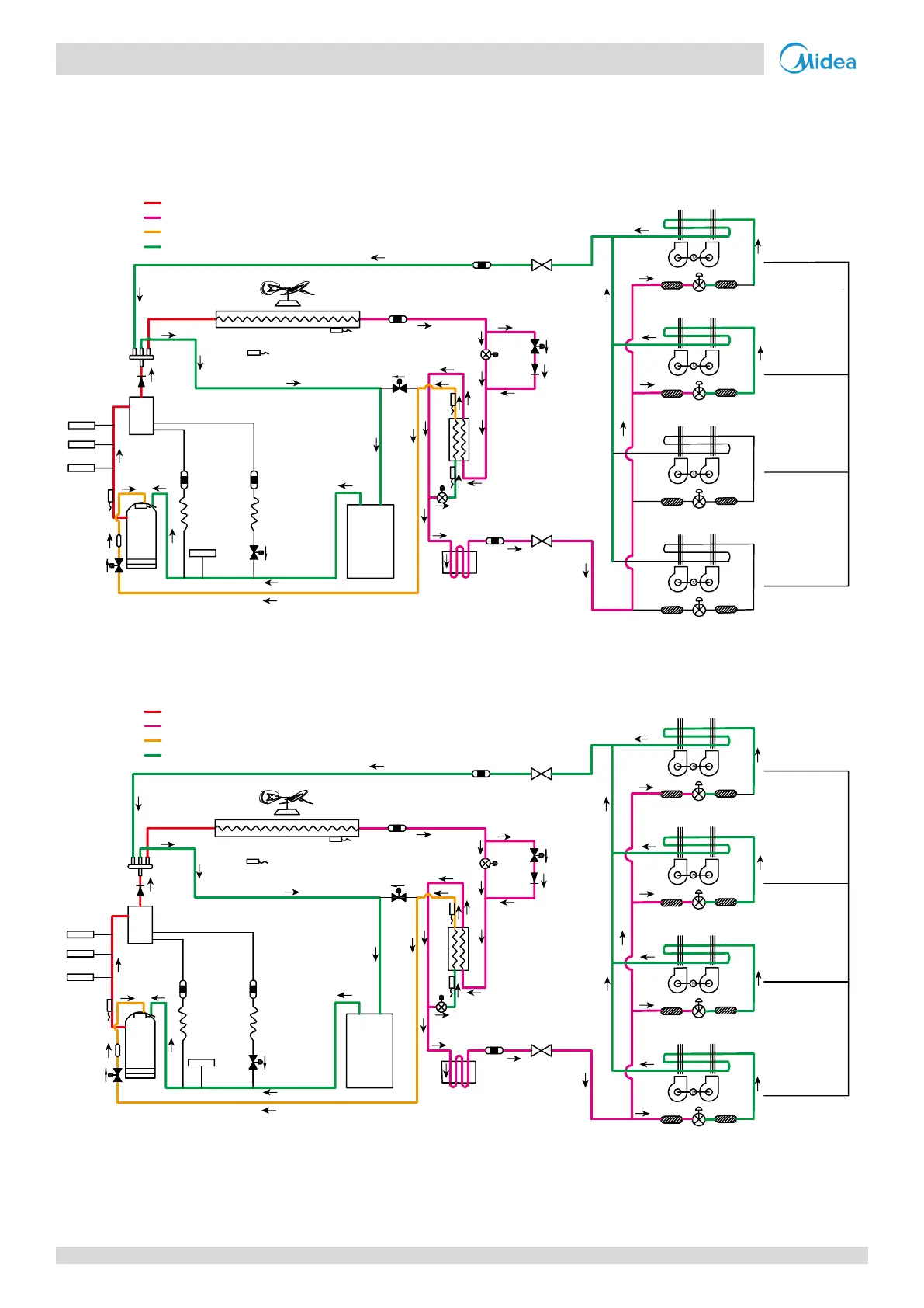
Cooling operation
Figure 2-3.1: 8/10/12HP refrigerant flow during cooling operation
Oil return operation in cooling mode
Figure 2-3.2: 8/10/12HP refrigerant flow during oil return operation in cooling mode
7
1
15
12
9
3
2
4
5
6
11
10
14
8
13
EXVA
EXVC
E
S
C
T3
T4
T6B
T7C1
T7C2
T6A
SV8A
SV4
SV5
SV6
Closed
Filter
Filter
Closed
Unit on
Thermostat off
Unit on
Thermostat on
Unit on
Thermostat on
Unit off
Filter
Indoor unit operation
Filter
Normal control
Filter
Filter
Normal control
Filter
Filter
High temperature, high pressure gas
High temperature, high pressure liquid
Medium temperature, medium pressure gas
Low temperature, low pressure
Fan
on
Fan
off
Fan
on
Fan
on
7
1
15
12
9
3
2
4
5
6
11
10
14
8
13
High temperature, high pressure gas
High temperature, high pressure liquid
Medium temperature, medium pressure gas
Low temperature, low pressure
EXVA
EXVC
E
S
C
T3
T4
T6B
T7C1
T7C2
T6A
SV8A
SV4
SV5
SV6
300 steps
Filter
Filter
300 steps
Unit on
Thermostat off
Unit on
Thermostat on
Unit on
Thermostat on
Unit off
Filter
Indoor unit operation
Filter
Normal control
Filter
Filter
Normal control
Filter
Filter
Fan
on
Fan
off
Fan
on
Fan
on

 Loading...