6
valves, so flush in a direction into the suc-
tion (bottom) connection, and out the dis-
charge (top) connection.
B. Cap or plug all openings to capture the inhibit-
ing fluid, and to prevent animals and insects
from building nests.
Pneumatic, Electrical and Electronic Equip-
ment
A. Motors should be prepared in the manner pro-
scribed by their manufacturer. If information is
not available, dismount and store motors as
indicated in step “B” below.
B. For all pneumatic and electrical equipment,
place packets of Vapor Phase Corrosion Inhibi-
tor (VPCI) inside of the enclosure, then place
the entire enclosure, with additional packets,
inside a plastic bag. Seal the bag tightly
closed. Contact Milton Roy Service Depart-
ment for recommended VPCI materials.
2.3 SAFETY PRECAUTIONS
WHEN INSTALLING, OPERATING, AND
MAINTAINING THE XT OR XW PUMP,
KEEP SAFETY CONSIDERATIONS
FOREMOST. USE PROPER TOOLS,
PROTECTIVE CLOTHING, AND EYE
PROTECTION WHEN WORKING ON
THE EQUIPMENT AND INSTALL THE
EQUIPMENT WITH A VIEW TOWARD
ENSURING SAFE OPERATION.
FOLLOW THE INSTRUCTIONS IN THIS
MANUAL AND TAKE ADDITIONAL
SAFETY MEASURES APPROPRIATE
TO THE LIQUID BEING PUMPED. BE
EXTREMELY CAREFUL IN THE
PRESENCE OF HAZARDOUS
SUBSTANCES (E.G., CORROSIVES,
TOXINS, SOLVENTS, ACIDS,
CAUSTICS, FLAMMABLES, ETC.).
THE PERSONNEL RESPONSIBLE FOR
INSTALLATION, OPERATION AND
MAINTENANCE OF THIS EQUIPMENT
MUST BECOME FULLY ACQUAINTED
WITH THE CONTENTS OF THIS MAN-
UAL.
ANY SERVICING OF THIS EQUIPMENT
MUST BE CARRIED OUT WHEN THE
UNIT IS STOPPED AND ALL PRES-
SURE HAS BEEN BLED FROM THE LIQ-
UID END. SHUT-OFF VALVES IN
SUCTION AND DISCHARGE SIDES OF
THE LIQUID END SHOULD BE CLOSED
WHILE THE UNIT IS BEING SER-
VICED. ACTIONS SHOULD BE TAKEN
TO ELIMINATE THE POSSIBILITY OF
ACCIDENTAL START-UP WHILE SER-
VICING IS TAKING PLACE. A NOTICE
SHOULD BE POSTED BY THE POWER
SWITCH TO WARN THAT SERVICING IS
BEING CARRIED OUT ON THE EQUIP-
MENT. SWITCH OFF THE POWER SUP-
PLY AS SOON AS ANY FAULT IS
DETECTED DURING OPERATION
(EXAMPLES: ABNORMALLY HIGH
DRIVE TEMPERATURE, UNUSUAL
NOISE, DIAPHRAGM FAILURE).
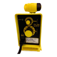
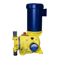
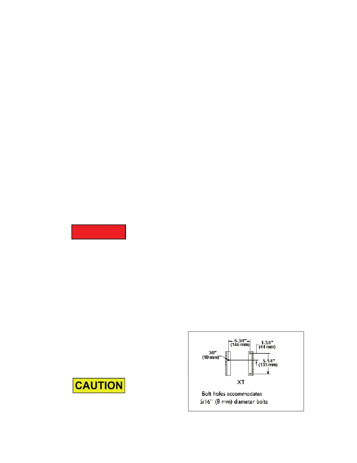
2.4 MOUNTING / LOCATION
The XT / XW pump can be mounted on any surface
that is flat and level for the pump base. Three
mounting bolt holes are provided in the XT pump
base (Figure 3) and the XW pump (Figure 4) for
use when the pump is to be firmly anchored to a
foundation surface.
Increased reliability can be expected if pump loca-
tions are avoided which are subjected to high
ambient temperatures (above 100°F (38°C) with
poor free-air circulation over the pump assembly.
Figure 3. XT Bolt Hole Dimensions

 Loading...