15
one full turn beyond this point to set a
reasonable buffer zone between operating
pressure and relief pressure. To determine if
relieving is taking place, insert your index
figure into the oil reservoir opening and place
it against the bypass opening where the oil
pulse from the relief valve can be
determined.
NOTE: No moving parts are present in the oil
reservoir in this location.
3. Reinstall plastic screw plug.
WHEN RELIEVING IS TAKING PLACE,
OIL MAY BE EJECTED AT HIGH
VELOCITY FROM THE BYPASS PORT.
NORMAL PRECAUTION SHOULD BE
OBSERVED TO PREVENT THIS FROM
SPLASHING THE SURROUNDING
AREA.
NOTE: This relief is intended primarily for
pump protection in the event that the discharge
or suction system is blocked while the pump is
in operation. It is a good practice to install a
high-grade chemical type relief valve in the
pump discharge line as close to the pump as
possible, and always between the pump and
any shut-off valve. Pipe the outlet of the sys-
tem relief valve back to the suction tank, with
the open end of the pipe visible at all times. In
this way, relief valve leakage may be easily
detected.
FOR SAFETY REASONS, A CHECK
VALVE IS RECOMMENDED FOR USE IN
THE DISCHARGE LINE NEAR THE
POINT WHERE THE LINE ENTERS A
HIGH-PRESSURE PROCESS VESSEL.
3.3 OPERATION
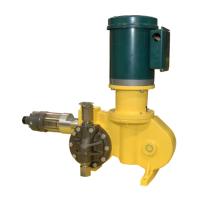
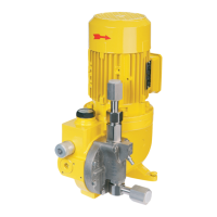
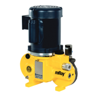
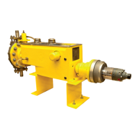
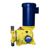
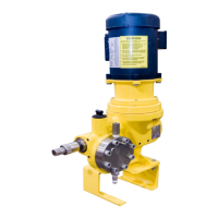
The mRoy pump is designed for reliable, unas-
sisted operation. During normal operation, a peri-
odic check of the pump is recommended every 24
or 48 hours to visually confirm satisfactory opera-
tion:
1. Make sure the oil level in air bleed filler
reservoir is above oil level mark.
2. Inspect pump liquid end for indication of
leakage or seepage.
If anything seems to be amiss, refer to Section 4,
Maintenance.
 Loading...
