2
1. The pump plunger reciprocates with a constant
stroke length and displaces oil into and out of the
diaphragm chamber.
2. The flexible diaphragm is a movable partition
between the plunger oil and fluid being pumped.
3. An oil bypass circuit from the plunger by-pass
ports to the reservoir.
In operation, on the discharge stroke, the pump
plunger and the capacity adjustment spool work to
regulate the amount of oil ( Figure 1), which is by-
passed to the oil reservoir. The plunger moves over
the control spool which closes off the by-pass
ports. The place where this occurs is dependent on
the capacity setting. Then the balance of the
plunger displacement is imposed on the flexible
diaphragm that moves and displaces the fluid
being pumped through the discharge ball check.
On the suction stroke, the pump plunger is pulled
away from the diaphragm cavity which decreases
the pressure of the hydraulic fluid. When the pres-
sure is decreased below that of the process fluid,
the process fluid is pushed through the suction ball
check, which then moves the flexible diaphragm.
When the by-pass ports reach the end of the con-
trol rod, the hydraulic cavity is opened to the reser-
voir and the balance of the plunger oil dis-
placement can be supplied from the reservoir
through the by-pass passages.
The discharge capacity is adjusted from 0-100% by
rotating the adjustment knob which moves the con-
trol spool so that the bypass port is closed at the
desired percentage of the total plunger stroke.
When the control spool is adjusted to 100% capac-
ity the bypass port will be positioned so that it is
opened at the very end of the suction stroke. Then
on the pressure stroke, the by-pass ports are
immediately closed so the entire plunger displace-
ment is imposed upon the flexible diaphragm.
With the control spool adjusted for 50% capacity
the by-pass ports will be positioned so that they are
opened when the plunger has completed one-half
of the suction stroke. On the next pressure stroke,
the oil displaced by the pump plunger will be by-
passed through the open ports to the reservoir for
the first 50% of the stroke before the by-pass ports
are closed by the control plunger. The remaining
50% of the plunger displacement will then be
imposed on the flexible diaphragm so that fluid is
discharged for only 50% of the plunger travel. A
similar analysis would apply for 0% capacity setting
on the control valve where all the plunger oil dis-
placement is by-passed to the reservoir.
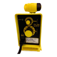
1.4 MODEL CODING
The model code can be found on the data plate
(Figure 2) attached to the pump. For a general
description of the mRoy pump you have pur-
chased, compare your model number to the prod-
uct codes shown on page 4.
1.5 SPECIFICATIONS
Plunger Diameters:
mRoy XT: 11/32" (9 mm)
mRoy XW: 1/2" (13 mm)
Pressures:
2000-3000 psig (138-207 bar g)
Liquid End Type:
Hydraulically Actuated Disc Diaphragm
Flow Range:
mRoy XT: 2.2 gph (8.3 liter/hr)
mRoy XW: 9.2 gph (34.8 liter/hr)
Materials of Construction:
Head: 316 SS
Seals: Viton or Buna N
Diaphragm: PTFE
(Custom Materials Available)
Flow Rates and Pump Model Coding
See www.miltonroy.com
Data Sheets for Download - mRoy Bulletin
3300
Steady State Accuracy/Turndown Ratio:
+/-1% steady state accuracy over 10:1
turndown ratio (w/constant speed drive).

 Loading...