2-6 T1 Service Manual
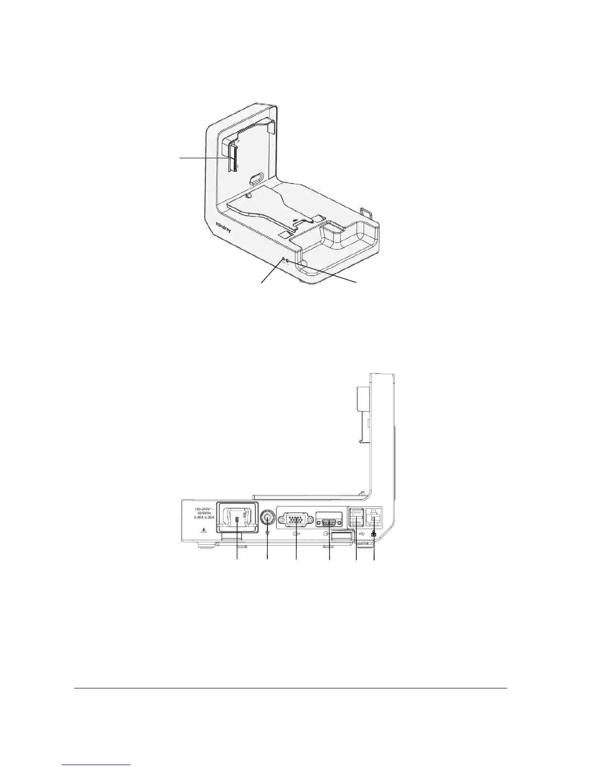
2.4.2 Right View
1. T1 docking station multi-pin connector: power input and communication connector of T1
2. Connection status indicator: it is on when the T1 is properly connected to the T1 docking station.
3. External power supply indicator: it is on when the external AC power supply is connected.
2.4.3 Rear View
1. AC power input
2. Equipotential grounding terminal
3. VGA connector: connects the external display
4. External device connector: connects T1 to the host monitor through the T1 docking station cable (P/N 009-003591-00 (1
meter) or P/N 009-003592-00 (4 meters)).
5. USB connector: connects USB devices, including the USB drive, mouse and keyboard.
6. Network connector: a standard RJ45 connector that connects the patient monitor to the CMS or CIS.
1
2
3
1
2
3
4
5
6
 Loading...