5. INSPECTION AND MAINTENANCE
5
−
3
5.2 Daily Inspections
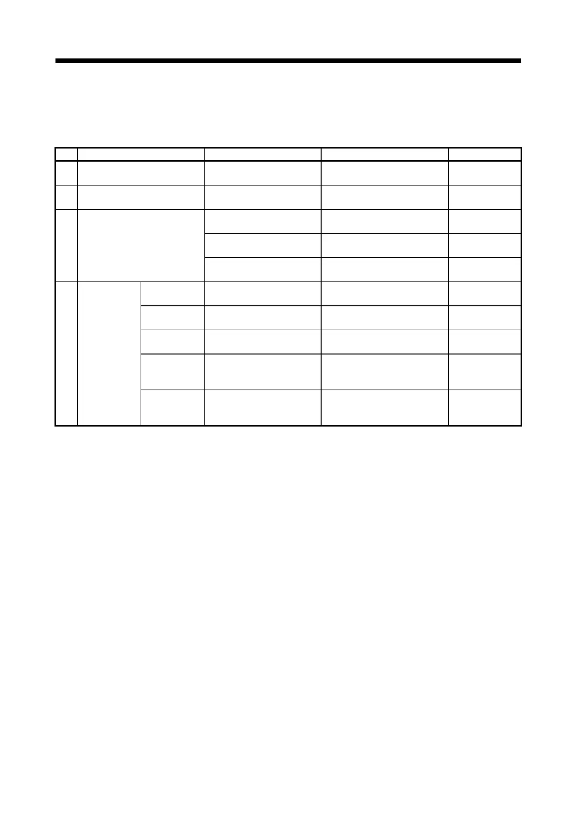
The inspections listed in the table below should be conducted every day.
Table 5.2 Daily Inspections
No. Item Description Evaluation Standard Remedy
1 Base unit installation
All screws tight and covers in
position.
Must be firmly installed.
Tighten loose
screws.
2 I/O(and other) module mounting
Modules correctly mounted in
base unit.
Fully mounted and screws
tightened.
Tighten loose
screws.
Terminal screws tight
Spacing between solderless
terminals.
Extension cable
connectors
No loose screws Correct spacing is maintained.
Connectors fully
tightened
3 Connections
Tighten loose screws Adjust spacing.
Tighten connector
screws
POWER
indicator
Check that indicator lights
Indicator lights
(otherwise abnormal)
See Section
5.4.1 (2)
RUN indicator Lights in RUN status
Indicator lights
(otherwise abnormal)
See Section
5.4.1 (3) (4)
ERROR
indicator
Lights when an error occurs.
Indicator not lit
(otherwise error)
See Section
5.4.1 (5) (6)
INPUT indicator
Check the indicator lighting
status.
Indicator lights when input is ON
and goes out when input is OFF
(otherwise abnormal).
See Section
5.4.1 (7)
4 Indicators
OUTPUT
indicator
Check the indicator lighting
status.
Indicator lights when output is ON
and goes out when output is OFF
(otherwise abnormal).
See Section
5.4.1 (7)
 Loading...