10
GB
9. Electrical wiring
Transmissioncablespecications
Transmissioncables MERemotecontrollercables MARemotecontrollercables
Typeofcable
Shieldingwire(2-core)
CVVS,CPEVSorMVVS
Sheathed2-corecable(unshielded)CVV
Cablediameter Morethan1.25mm
2
[AWG16]
0.3~1.25mm
2
[AWG22~16]
(0.75~1.25mm
2
[AWG18~16])*1
0.3~1.25mm
2
[AWG22~16]
(0.75~1.25mm
2
[AWG18~16])*1
Remarks
Maxlength:200m[656ft]
Maximumlengthoftransmissionlinesforcentralizedcontrolandindoor/
outdoortransmissionlines(Maximumlengthviaindoorunits):
500m[1640ft]MAX
Themaximumlengthofthewiringbetweenpowersupplyunitfor
transmissionlines(onthetransmissionlinesforcentralizedcontrol)and
eachoutdoorunitandsystemcontrolleris200m[656ft].
When10m[32ft]isexceeded,use
cableswiththesamespecication
astransmissioncables.
Maxlength:200m[656ft]
*1 Connectedwithsimpleremotecontroller. CVVS,MVVS:PVCinsulatedPVCjacketedshieldedcontrolcable
CPEVS:PEinsulatedPVCjacketedshieldedcommunicationcable
CVV:PVCinsulatedPVCsheathedcontrolcable
9.1. Power supply wiring
• Usededicatedpowersuppliesfortheindoorunit.
• Bearinmindambientconditions(ambienttemperature,directsunlight,rainwater,etc.)whenproceedingwiththewiringandconnections.
• Thewiresizeistheminimumvalueformetalconduitwiring.Ifthevoltagedrops,useawirethatisonerankthickerindiameter.Makesurethepower-supplyvoltage
doesnotdropmorethan10%.
• Specicwiringrequirementsshouldadheretothewiringregulationsoftheregion.
• Powersupplycordsofappliancesshallnotbelighterthandesign245IEC57,227IEC57,245IEC53or227IEC53.
• Aswitchwithatleast3mm[1/8in]contactseparationineachpoleshallbeprovidedbytheAirconditionerinstallation.
[Fig. 9.1.1] (P.4)
A
Ground-faultinterrupter
B
Localswitch/Wiringbreaker
C
Indoorunit
D
Pullbox
Totaloperatingcurrentofthe
Indoorunit
Minimumwirethickness(mm
2
)
Ground-faultinterrupter
*1
Localswitch(A)
Breakerforwiring(A)
(Non-fusebreaker)
Maincable Branch Ground Capacity Fuse
F0=16Aorless
*2
1.5 1.5 1.5 20Acurrentsensitivity
*3
16 16 20
F0=25Aorless
*2
2.5 2.5 2.5 30Acurrentsensitivity
*3
25 25 30
F0=32Aorless
*2
4.0 4.0 4.0 40Acurrentsensitivity
*3
32 32 40
ApplytoIEC61000-3-3aboutMax.PermissiveSystemImpedance.
*1 TheGround-faultinterruptershouldsupportInvertercircuit.
TheGround-faultinterruptershouldcombineusingoflocalswitchorwiringbreaker.
*2 PleasetakethelargerofF1orF2asthevalueforF0.
F1=Totaloperatingmaximumcurrentoftheindoorunits×1.2
F2={V1×(QuantityofType1)/C}+{V1×(QuantityofType2)/C}+{V1×(QuantityofType3)/C}+{V1×(QuantityofOthers)/C}
Indoorunit V1 V2
Type1
PLFY-NBMU,PMFY-NBMU,PEFY-NMSU,PCFY-NKMU,
PKFY-NHMU,PKFY-NKMU
18.6 2.4
Type2 PEFY-NMAU 38 1.6
Type3 PEFY-NMHSU 13.8 4.8
Others Otherindoorunit 0 0
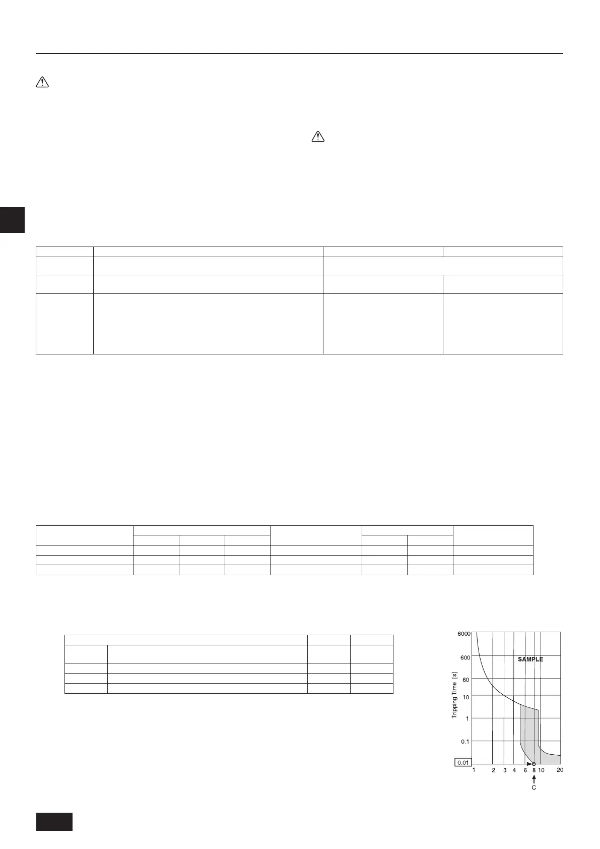
C:Multipleoftrippingcurrentattrippingtime0.01s
Pleasepickup“C”fromthetrippingcharacteristicofthebreaker.
<Exampleof“F2”calculation>
*ConditionPEFY-NMSU×4+PEFY-NMAU×1,C=8(refertorightsamplechart)
F2=18.6×4/8+38×1/8
=14.05
→
16Abreaker(Trippingcurrent=8×16Aat0.01s)
RatedTrippingcurrent(x)
Samplechart
Precautions on electrical wiring
Warning:
Electricalworkshouldbedonebyqualiedelectricalengineersinaccord-
ancewith“EngineeringStandardsForElectricalInstallation”andsupplied
installationmanuals.Specialcircuitsshouldalsobeused. If the power
circuitlackscapacityorhasaninstallation failure, it may cause a riskof
electricshockorre.
1. Besuretoinstallanearthleakagebreakertothepower.
2. Installtheunittopreventthatanyofthecontrolcircuitcables(remotecon-
troller,transmissioncables)isbroughtindirectcontactwiththepowercable
outsidetheunit.
3. Ensurethatthereisnoslackonallwireconnections.
4. Somecables(power,remotecontroller,transmissioncables)abovetheceil-
ingmaybebittenbymouses.Useasmanymetalpipesaspossibletoinsert
thecablesintothemforprotection.
5. Neverconnectthepowercabletoleadsforthetransmissioncables.Other-
wisethecableswouldbebroken.
6. Besuretoconnectcontrolcablestotheindoorunit,remotecontroller,and
theoutdoorunit.
7. Puttheunittothegroundontheoutdoorunitside.
8. Selectcontrolcablesfromtheconditionsgiveninpage10.
9. PerformwiringincompliancewiththesafetyregulationsdetailedinUL1995.
Caution:
• Besuretoputtheunittothegroundontheoutdoorunitside.Donot
connectthe earthcabletoanygaspipe,waterpipe,lighteningrod,or
telephoneearthcable.Incompletegroundingmaycauseariskofelec-
tricshock.
• Ifthesupplycordisdamaged,itmustbereplacedbythemanufacturer,
itsserviceagentorsimilarlyqualiedpersonsinordertoavoidahaz-
ard.

 Loading...