9
GB
7.2. Drainpipingwork
• Observe the following precautions when installing drain piping.
• Makesurethedrainpipinghasadownwardslopeofatleast1:100.
• To prevent the heat exchanger from being corroded and foul odor from being
emitted, do not place drain pipes in a drainage channel where sulfuric gas is
generated.
• Installdrainpipingsothattherearenoleaksfrompipingconnections.
• Adequately insulate the pipes to prevent condensation water from dripping.
- When running a drain hose in a ceiling where it is high in temperature and
humidity (dew-point temperature of 26 °C [79 °F] or higher) and operating
the units for a long time at a time, condensation may form on the drain
hose.Insulatethedrain hose or takeotherappropriatemeasurestopre-
vent condensation water from dripping.
• Insulate the drain pipe that runs through a room with commercially available
insulator (polyethylene foam with specific gravity of 0.03 and a minimum
thicknessof10mm[7/16in]).
1
When installing a unit on the top floor or in a high-temperature high-
humidityenvironment,useaninsulatorwith greater thickness than what
isspeciedabove.
2
Followthespecicationsspeciedbyyourclient,ifany.
• At the completionof installation, visually check thatdrain water is properly
drainedbylookingthroughthesightglassontheunitandcheckingtheexit
of the drain pipe.
Precautionsfordrainpipinginstallation
• Makesurethedrainpipinghasadownwardslopeofatleast1:100(drainage
side down).
• Insulate the drain pipe with a commercially available insulator.
• Thehorizontalrunofdrainpipingmustbe20m[65ft]orshorter.
(Ifthepiperunislong,installpipesupportstokeepthepipingfromtwisting.)
Don'ts
• Do not install an air vent. (Drain water may spew out.)
• Donotmakeanupwardrunoratrapinthepiping.
Centralizeddrainagesystem
• Approximately 10 cm [3-15/16 in] below the drain water outlet.
• Use a VP30 pipe, and provide a downward slope of at least 1:100.
[Fig.7.2.1](P.3)
Correct piping
Wrong piping
A
Insulation (9 mm [3/8 in] or more)
B
Downward slope (1/100 or more)
C
Support metal
K
Air bleeder
L
Raised
M
Odor trap
Grouped piping
D
O. D. ø32 mm [1-1/4 in] PVC TUBE
E
Makeitaslargeaspossible.About10cm[3-15/16in].
F
Indoor unit
G
Makethepipingsizelargeforgroupedpiping.
H
Downward slope (1/100 or more)
I
O. D. ø38 mm [1-1/2 in] PVC TUBE for grouped piping.
(9 mm [3/8 in] or more insulation)
J
Up to 700 mm [21-9/16 in]
N
Drainsocket(accessory)
O
Horizontalorslightlyupgradient
1. Insert the drain hose (accessory) into the drain port (insertion margin: 25 mm
[1 in]).
(The drain hose must not be bent more than 45° to prevent the hose from
breakingorclogging.)
(Attachthehosewithglueforthehardvinylchloridepipe,andxitwiththe
band (small, accessory).)
2. Attachthedrainpipe(O.D.ø32PVCTUBE,eldsupply).
(Attachthepipewithglueforthehardvinylchloridepipe,andxitwiththe
band (small, accessory).)
3. Performinsulationworkonthedrainpipe(O.D.ø32PVCTUBE)andonthe
socket(includingelbow).
4. Checkthedrainage.(Referto[Fig.7.3.1])
5. Attachtheinsulatingmaterial(accessory),andxitwiththeband(large,ac-
cessory) to insulate the drain port.
[Fig.7.2.2](P.3)
A
Indoor unit
B
Tie band (large) (accessory)
C
Visible part
D
Insertion margin
E
Drainsocket(accessory)
F
Drainpipe(O.D.ø32mm[1-1/4in]PVCTUBE,eldsupply)
G
Insulatingmaterial(eldsupply)
H
Tie band (small) (accessory)
7.3. Conrmingdraindischarge
u
Makesurethatthedrain-upmechanismoperatesnormallyfordis-
chargeandthatthereisnowaterleakagefromtheconnections.
• Besuretoconrmtheaboveinaperiodofheatingoperation.
• Besuretoconrmtheabovebeforeceilingworkisdoneinthecaseofanew
construction.
1. Remove the maintenance panel.
2. Pour 1000 cc of clean water into the drain pan.
Note: Ifusingapumptosupplywater,adjustthewaterowrateto0.4L/min
or slower by adjusting the valve. Supplying water at a faster rate may
causewaterleakagefromindoorunitsordamagethedrainpump.
3. Operate the units in the emergency mode, add clean water as necessary,
andcheckforproperdrainwaterdrainagethroughthedrainwatersight
glass.
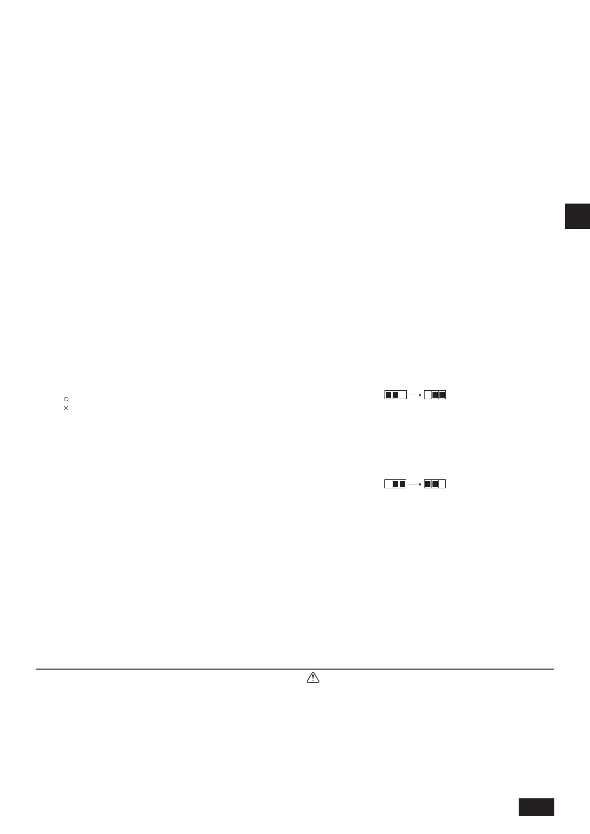
To operate the units in the emergency mode, disconnect the connector from
the OFF side of SWE on the control board in the control box. Then, connect
it to the ON side to supply power and simultaneously operate the drain pump
and the fan.
SWE SWE
OFF ON OFF ON
Atthecompletionofwork,besuretoplacetheconnectorbacktoitsoriginal
position.
Note: Before covering the sight glass on the drain port with an insulator,
ashalightonittocheckforproperdrainage.
4. Whendone,besuretoplacetheconnectoronSWEbacktoitsoriginal(OFF)
position,andplacethemaintenancepanelbackon.
SWE SWE
OFF ON OFF ON
• After removing the insulator to check the drain water through the sight
glass,replacetheinsulator.
[Fig.7.3.1](P.3)
A
Insert pump's end 2 to 4 cm [13/16-1-5/8 in].
B
Maintenance panel
C
About 1000 cc
D
Water
E
Filling port
8.Ductwork
• When connecting ducts, insert a canvas duct between the main body and the
duct.
• Use non-combustible duct components.
• Install sufcient thermal insulation toprevent condensation forming onair
inletandairoutletductanges,andairoutletducts.
[Fig. 8.0.1] (P.4)
A
Air inlet
B
Airlter(suppliedatsite)
C
Duct
D
Canvas duct
E
Access door
F
Ceiling
G
Ensuresufcientlengthtopreventshortcycling
H
Air outlet
Caution:
Inletductis850mm[33-1/2in]ormorenecessarytoconstruct.
Alwaysinstallhorizontal.
 Loading...