3
1
8 2
3
3. Function and electric wiring of interface each part
4
2
3
2
5
3
5
6
72
9
3
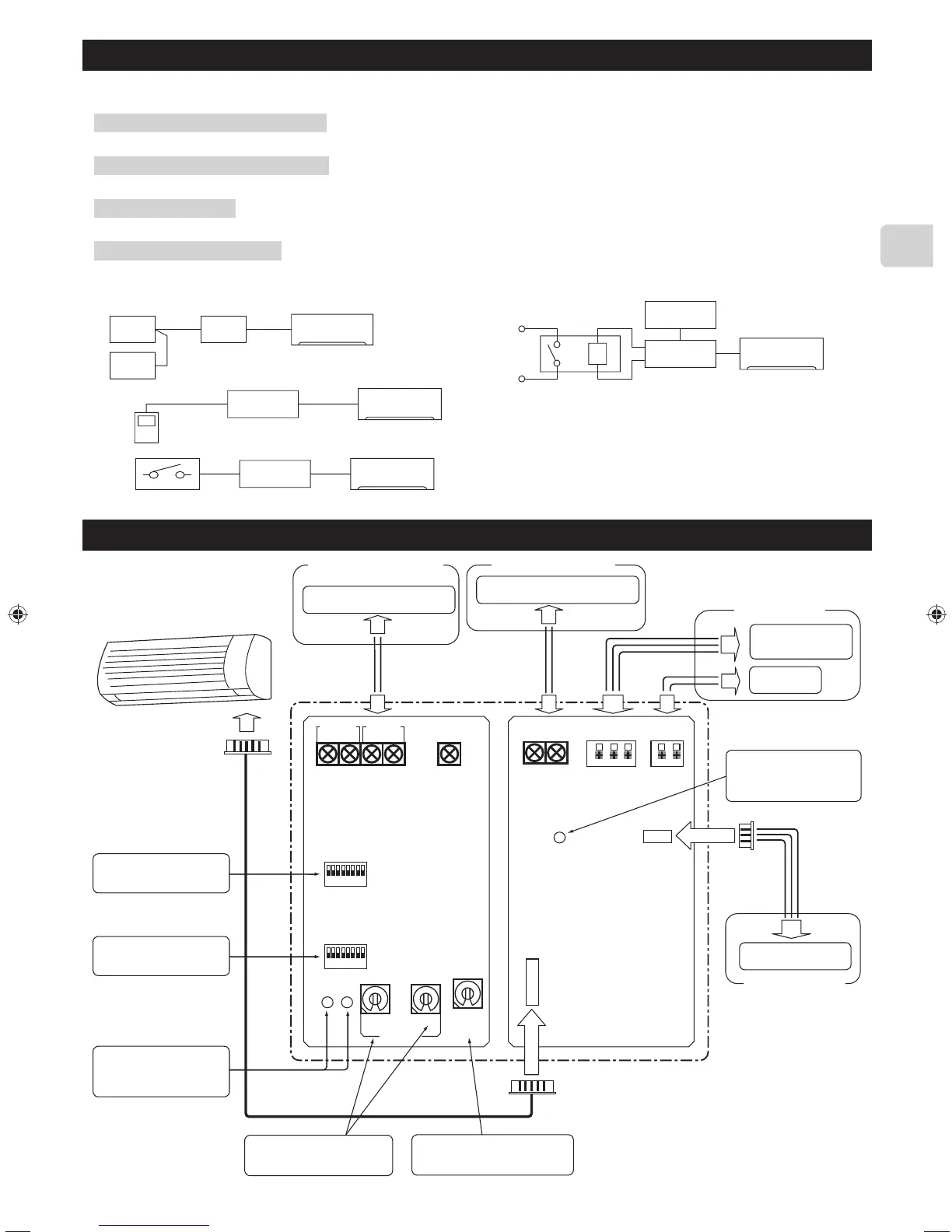
2. Before Installation
How to Use the SYSTEM CONTROL Interface.
■Functions
Connecting with M-NET system (Fig. 2-1)
The room air conditioner can be managed centralized or individually by the system controller using M-NET communications control.
Used as wired remote controller (Fig. 2-2)
MA remote controller can be used as a wired remote controller.
Remote control (Fig. 2-3)
Contact signals enable inputting of ON/OFF, prohibiting/allowing operation, and heating/cooling.
Status indicator output (Fig. 2-4)
Signals of ON/OFF, error/normal, heater ON/OFF, and humidifier ON/OFF are output.
■Sample System Configuration
Fig. 2-1
Fig. 2-2
Fig. 2-3
Fig. 2-4
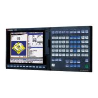
1 System controller, etc
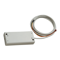
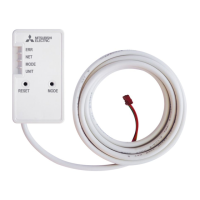
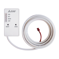
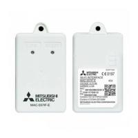
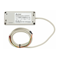
2 SYSTEM CONTROL
Interface
3 Indoor Unit
4 MA remote controller
5 Contract point
6 Relay
7 Coil
8 Power supply unit for
M-NET transmission line
9 External power supply
for DC 12 V
TB521
S
B A R2 R1 C
-
+
SW500
SW502
SW580
LE501
TB580 MA
TB571 TB530
CN591
CN560
TB520
LE502
LE581
B2 A2 B1 A1
12345678
12345678
MA
SW501 SW510
00
0
Indoor unit
To use centralized control by
M-NET
MELANS system controller
To use MA remote controller
MA remote controller
Status of room air
conditioner output
DC power
supply (12 V)
To CN105
M-Net2
M-Net1
(Sky Blue)
(Gray)
Card key, Coin timer, etc.
To input control signal
and control room air
conditioner remotely
ON
ON
(Orange)(Red)
M-Net
(Orange)
(White)
(White)
Refrigerant address setting switch
*Refer to section 9 “Connecting with
MA remote controller” for details.
M-NET address setting switch
*Refer to section 8 “Connecting
with M-NET system” for details.
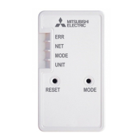
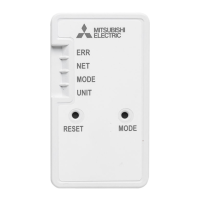
LED for checking communica-
tions with connected equipment
*Refer to section 13 “Interface
status monitor” for details.
Function setting switch B
*Refer to section 4 “Dip
Switch Details” for details.
Function setting switch A
*Refer to section 4 “Dip
Switch Details” for details.
LED for checking communica-
tions with connected equipment
*Refer to section 13 “Interface
status monitor” for details.
Relay items, such as
heater and humidifier, etc.
connected to the relay.
JG79Y451H01EN.indd3 2018/06/1317:01:54
 Loading...