5
6.
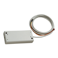
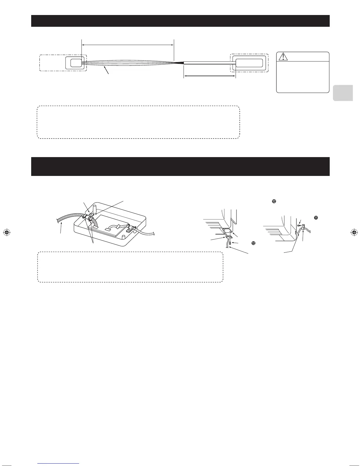
Connecting the SYSTEM CONTROL Interface to a room air conditioner
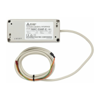
● Connect the interface unit ➊ and the indoor control board of a room air conditioner using the connecting cable (5-core) that comes with the interface
unit ➊.
Room air conditioner
Indoor
controller
board
Thin part of the connecting cable
Make sure to wire and shield the cable
so that the customer does not contact it.
Connect the connecting cable (5-core) that comes with
the interface unit
➊
to the connector CN105 on the indoor
control board of a room air conditioner.
Thick part of the
connecting cable
Interface unit ➊
Connecting
connector
Warning
Securely fix the
connecting cable in
the designated place.
Failure to do so may
cause an electric shock,
fire, or malfunction.
● The connecting cable (5-core) connected to a room air conditioner should be wired according to the room air conditioner installation manual.
CN105
(CN92)
Notes
• Extending or shortening the connecting cable (5-core) that comes out of the interface unit
➊
cause it to malfunction. Also, keep the connecting cable (5-core) as far as possible away from the
electrical wires and ground wire. Do not bundle them together.
• To prevent the board from being damaged by static electricity, always remove static electricity
before starting work.
7. Connecting the SYSTEM CONTROL Interface with each system
● Screw the mounting cord clamp ➍~➏ according to the thickness of the
connecting cable used for each system. Fasten the cable tie ➑ as shown
in the figure to prevent undesirable movement of the connecting cable.
● The connecting cable (5-core) connected to a room air conditioner
should be mounted at the room air conditioner or its vicinity.
If the screw for the cable mount of the room air conditioner cannot be
used, replace with the screw for mounting
.
Screw ➐
Connecting cable
for each system
Cable tie ➑
Mounting cord clamps ➍~➏
Mounting
cord clamp
➎
Cable mount
Connecting cable
(5-core)
Mounting
cord clamp
➎
Screw
Screw
● Conduct the settings of the interface unit
➊
dip switch (SW500, SW502) and rotary switch (SW501, SW510, SW580) before turning on the power.
Notes
• If the connecting cable is not securely mounted, the connector may come off, break, or
malfunction.
• The dip switch (SW500, SW502) and the rotary switch (SW501, SW510, SW580) on the
interface unit
➊
do not operate if they are not set correctly.
(For details on each system, see the relevant instruction manual.)
JG79Y451H01EN.indd5 2018/06/1317:01:55
 Loading...