-
102
-
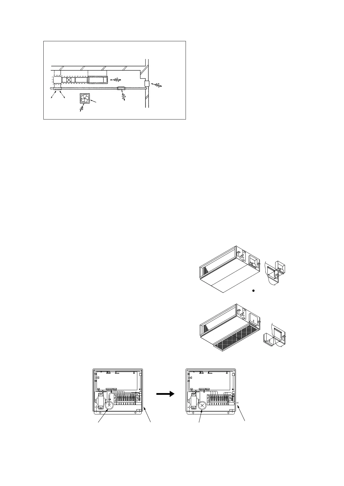
Bad example of duct work
For ventilation
Louver to
outdoor ai
Outlet of control wiring Outlet of crossover wiring Outlet of crossover wiring Outlet of control wiring
7) If a duct is not provided at the suction side but it is substituted with the space over the ceiling, humidity in the space will
increase by the influence of capacity of ventilation fan, strength of wind blowing against the out door air louver, weather
(rainy day) and others.
a) Moisture in air is likely to condense over the external plates of the unit and to drip on the ceiling.
Unit should be operated under the conditions as listed in the above table and within the limitation of wind volume.
When the building is a concrete structure, especially immediately after the construction, humidity tends to rise even
if the space over the ceiling is not substituted in place of a duct.
In such occasion, it is necessary to insulate the entire unit with glass wool (25mm). (Use a wire net or equivalent to
hold the glass wool in place.)
b) It may run out the allowable limit of unit operation (Example: When outdoor air temperature is 35˚C DB, suction air
temperature is 27˚C WB) and it could result in such troubles as compressor overload, etc..
c) There is a possibillty that the blow air volume may exceed the allowable range of operation due to the capacity of
ventilation fan or strength of wind blowing against external air louver so that drainage from be heat exchanger may
fail to reach the drain pan but leak outside (e. g. drip on to the ceiling) with consequential water leakage in the room.
(f) Control box (Only case of FDURA401, 501)
● During bottom side suction, the orientation of the control box can be changed to allow the control box to be maintained
from the inlet port.
1) Remove the bottom plate (on the inlet port side),
and all wiring connectors from the control box.
2) Remove the three screws that fasten the cabinet inside the
control box.
3) Pull the control box toward the outside of the unit.
4) Change the ejection of the wiring inside the control box.
5) Fit the control box from the inside of the unit.
6) Fit the three screws that fasten the cabinet.
7) Correctly connect all wiring connectors.
Before shipment from the
plant, arrangements are made
to enable maintenance from
the sides of the unit.
 Loading...