-
106
-
S Models FDCA801, 1001 only
(a) Selecting the installation location
1) Where air is not trapped. 5)
Where it is safe for the drain water to be discharged.
2)
Where the installation fittings can be firmly installed.
6)
Where noise and hot air will not bother neighboring residents.
3)
Where wind does not hinder the intake and outlet pipes.
7) Where snow will not accumulate.
4) Out the heat range of other heat sources. 8)
Where strong winds will not blow against the outlet pipe.
Notes(1) A four-sided enclosure cannot be used. Leave a space of at least 1m above the unit.
(2) If there is a danger of a short-circuit, then install a wind direction variable adapter.
(3) When installing multiple units, provide sufficient intake space so that a short-circuit does not occur.
(4) In areas where there is snowfall, install the unit in a frame or under a snow hood to prevent snow from accumulating on it.
(Inhibition of collective drain discharge in a snowy country)
(5) Do not install the equipment in areas where there is a danger of flammable gas leaks.
*
Please ask your distributor about optional parts such as wind vane adapters, snow guard hoods, etc.
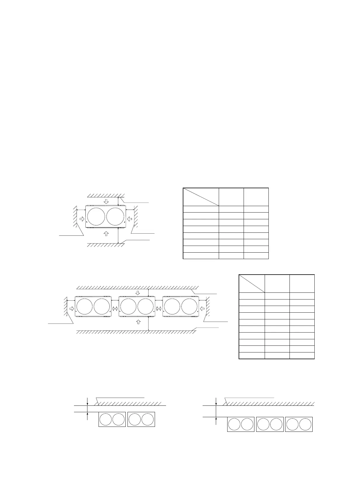
(b) Installation space (service space) example
Please secure sufficient clearance (room for maintenance work, passage, draft and piping). (If your installation
site does not fulfill the installation condition requirements set out on this drawing, please consult with your
distributor or the manufacturer)
1) When one unit is installed
2) When more than one unit are installed.
Dimensions
L1
L2
L3
L4
H1
H2
H3
H4
12
500
10
100
10
1500
No limit
1000
No limit
Open
10
100
Open
–
No limit
No limit
–
Example
installation
Unit: mm
Dimensions
L1
L2
L3
L4
L5
L6
H1
H2
H3
H4
12
500
10
100
10
0
0
1500
No limit
1000
No limit
Open
200
300
Open
400
400
No limit
No limit
No limit
No limit
Example
installation
Unit: mm
Wall height H3
Wall height H4
Service
space
Installation space
Wall height H1
Wall height H2
Air inlet
Air inlet
Air
inlet
Air
inlet
L1 L3
L4L2
()
Installation space
Wall height H2
Air
inlet
Air
inlet
Air
inlet
Air
inlet
L2 L5 L6 L4
Air inlet
Air inlet
L3L1
Wall height H3
Wall height H4
Wall height H1
Service
space
()
3) Multiple unit installation (Multiple longitudinal and vertical and horizontal rows installed)
• Pattern 1 • Pattern 2
3-side Intake Example 1 (2 units) 3-side Intake Example 2 (3 units)
Front
Open
300 or greater
Wall height not restricted
Wall height not restricted
Front
Open
100 or greater
 Loading...