-
85
-
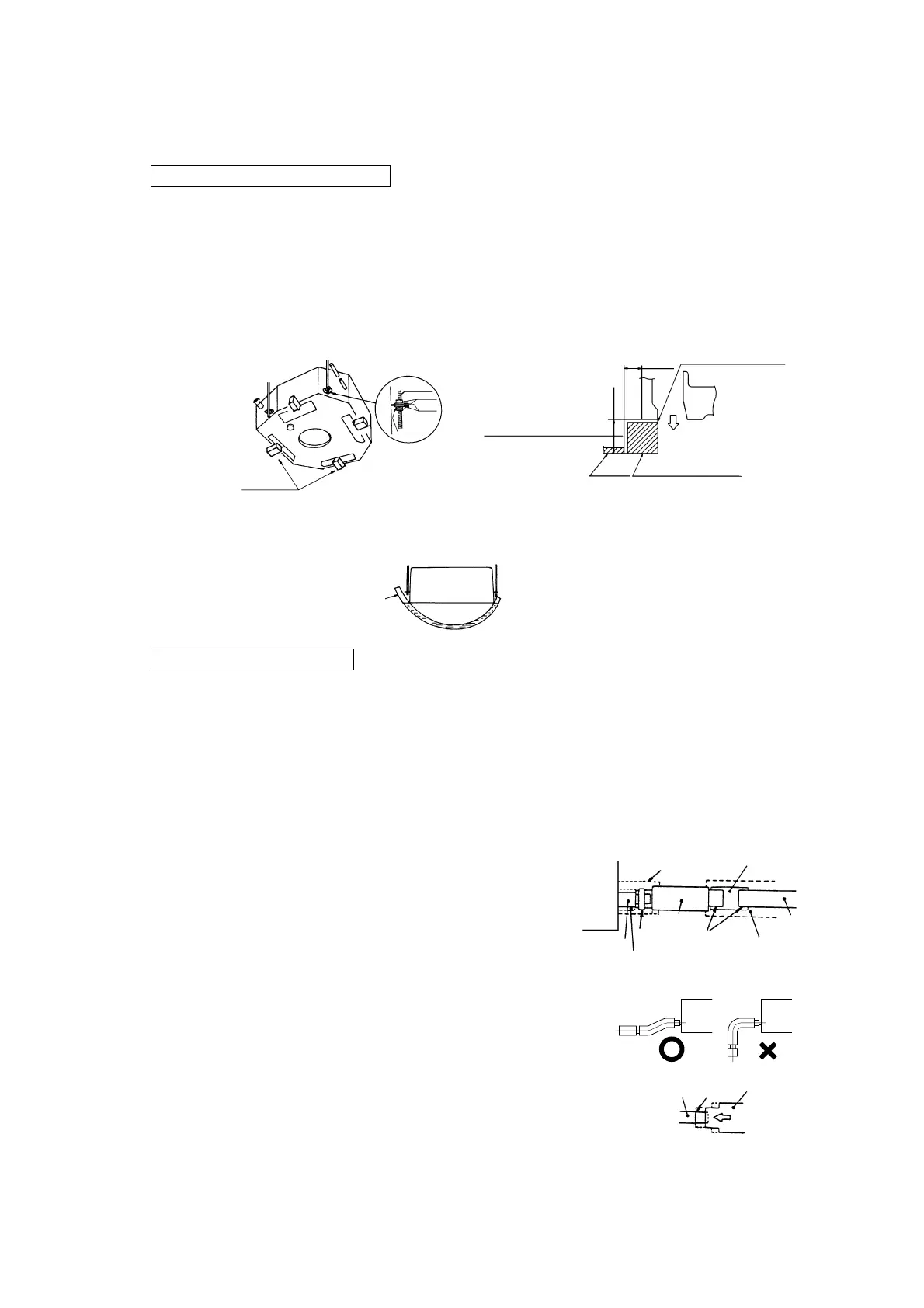
(c) Suspension
¡ Please arrange four sets of a suspension bolt (M10 or M8), a nut matching the bolt, a flat washers and a spring washer on
the installation site.
When suspension from the ceiling
1) In the case of the standard series: Cut and opening of 860~890.
In cutting an operating on the ceiling, use the unit’s cardboard container for shipment as a reference of the size of
opening.
¡ The center of the opening on the ceiling must accord with the center of the unit.
2) Determine the positions of suspension bolts (675×780).
3) Use four suspension bolts, each fastened in such a manner that it can withstand pull force of 50 kgf.
4) Make suspension bolts to the length that leaves approximately 70 mm of them above the ceiling.
5) After hoisting in the unit, attach level gauges supplied as accessories and determine the unit position (height).
6) Use a transparent tube with water filled inside to check the level of the unit. (A tolerable height difference at an end of the
unit is within 3 mm)
When embedded into ceiling
1) Determine the positions of suspension bolts (675×780).
¡ The pitch center of a suspension bolt must accord with the center of the unit.
2) Use four suspension bolts, each fastened in such a manner that it can withstand pull force of 50 kgf.
3) In cutting an opening on the ceiling, use the unit’s cardboad container for shipment as a reference of the size of opening.
4) Fix the unit as per A-5 and 6 above.
¡ The unit’s cardboard container for shipment can be used to cover the indoor unit.
Note (1): When a hanging bolt exceeds 1.3 m in length, use an M10 bolt and give it reinforcements such as braces.
Refrigerant piping
Drain
bolt
Suspension
Nut
Washer
Spring
Washer
Main
body
Level gauge
10~25
mm
33~38
mm
Supply air grill
Adjust so that the level gauge surface and
the lower surface of ceiling are in matching.
Fix the level gauge in alignment
with this face of supply air grill.
Ceiling
material
Level gauge (insulation)
Indoor unit
Hose
Drain socket
Clamp
(accessory)
No adhesive allowed
Pipe cover (large)
[for insuation]
(accessory)
Joint for VP25
(not included)
Drain hose
(accessory)
Indoor
unit
Adhesion
Pipe cover (small)
[for insuation]
(accessory)
Pipe cover
[for insuation]
(not included)
VP25
(not included)
Drain hose
Stepped
part
Drain socket
1) Glue the drain hose supplied as an accessory and a VP-25 joint before
lifting the unit.
2) The drain hose is to provide a buffer to absorb a slight dislocation of the
unit or the drain piping during installation work. If it is subject to abuse
such as being bent or pulled deliberately, it may break, which will result
in a water leak.
3) Care must be taken so as not to allow an adhesive to run into the drain
hose. When it is hardened, it can cause a breakage of a flexible part, if the
flexible part receives stress.
4) Use VP-25 general-purpose hard PVC pipes for drain piping.
5) Insert the drain hose supplied as an accessory (soft PVC end) to the stepped
part of the unit’s drain socket and then fasten it with the clamp also sup-
plied as an accessory.
6) Adhesive must not be used.
a) Glue a VP-25 joint (to be procured locally) to joint it with the drain
hose (hard PVC end) and then glue a VP-25 (to be procured locally)
to the joint.
(d) Drain Piping
 Loading...