-
143
-
(4) Error diagnosis procedures at the outdoor units side
At the error diagnosis related to the outdoor unit, check at first the error code of remote controller and the illumination patterns of
norma1 and inspection display lamps in the same manner as the case of indoor unit.
Then estimate the outline, the cause and the location of error based on the pattern and proceed to the inspcetion and repair.
Since the self diagnosis function by means of the microcomputers of indoor/outdoor units provide the judgement of error of
microcomputers them selves irregularity power supply line, overload, etc. caused by the installation space, inadequate volume of
refrigerant etc., the location and cause of trouble will be discovered without difficulty.
In addition, the display lamps error code of indoor/outdoor unit is kept flashing, (except when the power supply is iterrupted) after
the irregularity is automatically recovered to give irregularity information to the service presonnel. If any mode of higher priority
than the error retained in memory occurs after the reset of error, it is switched to that mode and saved in the memory.
(a) Replacement parts assembly related to the outdoor unit controller
Outdoor unit PCB, capacitor, thermistor, (heat exchanger, discharge pipe, outdoor temperature, under-doom), fuse, trans-
former, etc.
(b) Replacement procedure of outdoor unit microcomputer printed circuit board.
Microcomputer printed circuit board can replaced with following procedure.
1) Confirm the parts numbers. (Refer to the following parts layout drawing for the location of parts number.)
Applicable Model
FDCA301HEN, 401HEN
FDCA301HES, 401HES, 501HES, 601HES
FDCA801HES, 1001HES
PCA505A065ZP
PCA505A065ZT
PCB505A042PB
Parts No.
1 2 3 4 5 6
ON
1 2 3 4 5 6
ON
1 2 3 4 5 6
ON
1 2 3 4 5 6
ON
1 2 3 4 5 6
ON
1 2 3 4 5 6
ON
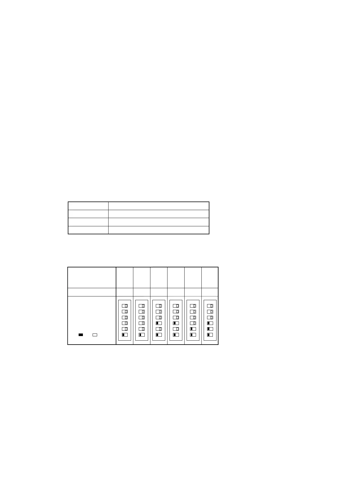
17 2710
Switch Setting Table
Set the switches ON or
OFF for each switch
No.
( ON, OFF)
Model
Setting Value (A)
FDCA
301HEN
FDCA
301HES
FDCA
401HEN
11 1412
FDCA
401HES
FDCA
501HES
FDCA
601HES
2) Set the overcurrent value using the overcurrent setting switch for CM (SW3). (In the case of the FDCA301~601 only)
Switch Setting Table (All switches are set in the OFF position when shipped from the factory.)
3) Set the control select switch to match the previously set settings on the previous board.
If the previously set settings were set with jumper wires, the control select switch should be set in the ON position if there
was a jumper wire and in the OFF position if there wasn’t a jumper wire.
4) Connect the faston terminals and connectors to the control board.
When connecting the wires to the faston terminals, connect each wire to the terminal printed with the same color on the
board.
Note (1) When connecting the faston terminals to the control PCB, connect them so that there is no deformation of the far end of the control PCB.
 Loading...