6 - 8
6.
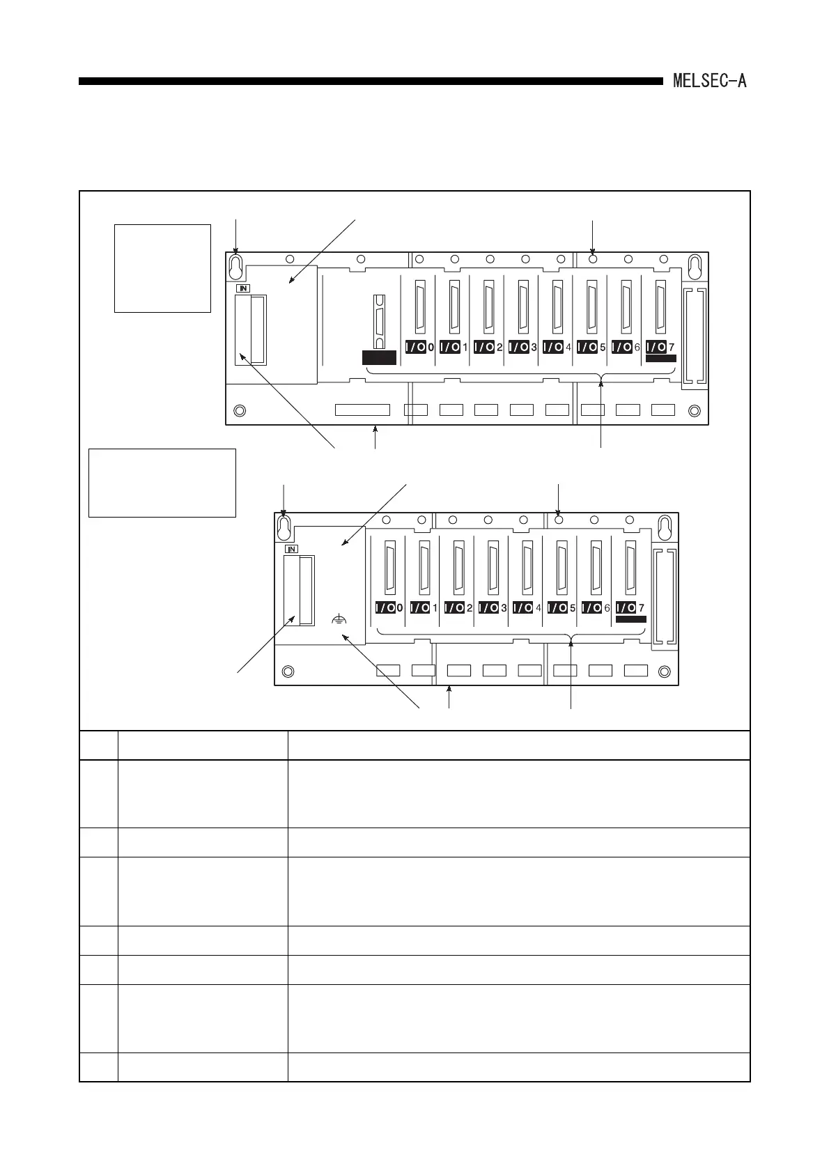
(2) Extension base unit (A1S52B, A1S55B, A1S58B, A1S52B-S1, A1S55B-S1, A1S58B-
S1, A1S65B, A1S68B, A1S65B-S1, A1S68B-S1)
No. Name Description
1) Extension cable connector A connector used to connect an extension cable, by which signals can be
transferred to/from an main base unit.
Before connecting the extension cable, remove the supplied connector cover.
2) Base cover A protective cover for the extension cable connector.
3) Module connector Connectors used to install the power supply module, I/O modules and/or special
function modules. To prevent dust from entering, install the supplied connector
cover or a blank cover (A1SG60) to any open connector.
4) Module mounting screw hole Screw mounting hole to fix the module to the base. Screw size: for M4 screw
5) Base installation hole A bell-shaped hole used to install the base unit to a control panel. (For M5 screw)
6) Hook for DIN rail Hook for DIN rail installation.
A1S52B, A1S55B, A1S52B-S1, A1S55B-S1...........................................1 pc
A1S65B, A1S68B, A1S58B, A1S65B-S1, A1S68B-S1, A1S58B-S1.......2 pcs
7) FG terminal The ground terminal connected to the shielding pattern of the printed-circuit board.
POWER
A1S58B
A1S68B
5)
2)
4)
3)
6)
1)
5)
2)
4)
3)
6)
7)
1)
(FG)
A1S65B,
A1S68B,
A1S65B-S1,
A1S68B-S1
A1S52B, A1S55B,
A1S58B, A1S52B-S1,
A1S55B-S1, A1S58B-S1
BASE UNIT AND EXTENSION CABLE
 Loading...


