2 - 1
2. SYSTEM CONFIGURATION
2 SYSTEM CONFIGURATION
The possible system configuration with A2USHCPU-S1, A2USCPU(S1), A2ASCPU(S1/
S30), and the precautions when the system is configured, and system conponents are
described.
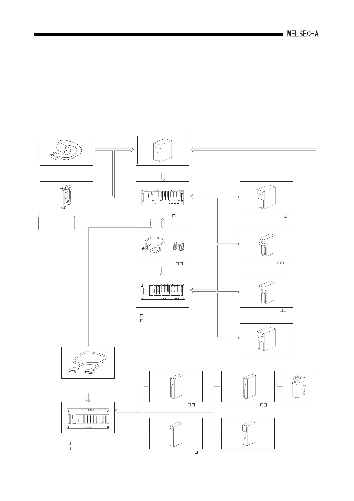
2.1 Overall Configuration
The system configurations of the A2USHCPU-S1, A2USCPU(S1), A2ASCPU(S1/S30)
stand-alone systems and peripheral devices are shown as follows:
Power supply module (A1S6 P)
To peripheral devices
A2USHCPU-S1, A2USCPU(S1), A2ASCPU(S1/S30)
Battery (A6BAT)
Special function module
Power suppy module (A6 P)
Special function module
Fuse
Main base (A1S3 B)
Extension cable(A1SC B)
Output module (A1SY )
Input module (AX )
Output module (AY )
Input module (A1SX )
Extension base
(A1S5 B(S1)): without a power
(A1S6 B): with a power supply module
Connection cable(A1SCO5NB)
[For building-block type]
Extension base
(A5 B): without a power supply module
(A6 B): with a power supply module
Memory casette
(A2SNMCA-30KE
with E
2
PROM)
 Loading...


