4 - 46
CPU MODULE4.
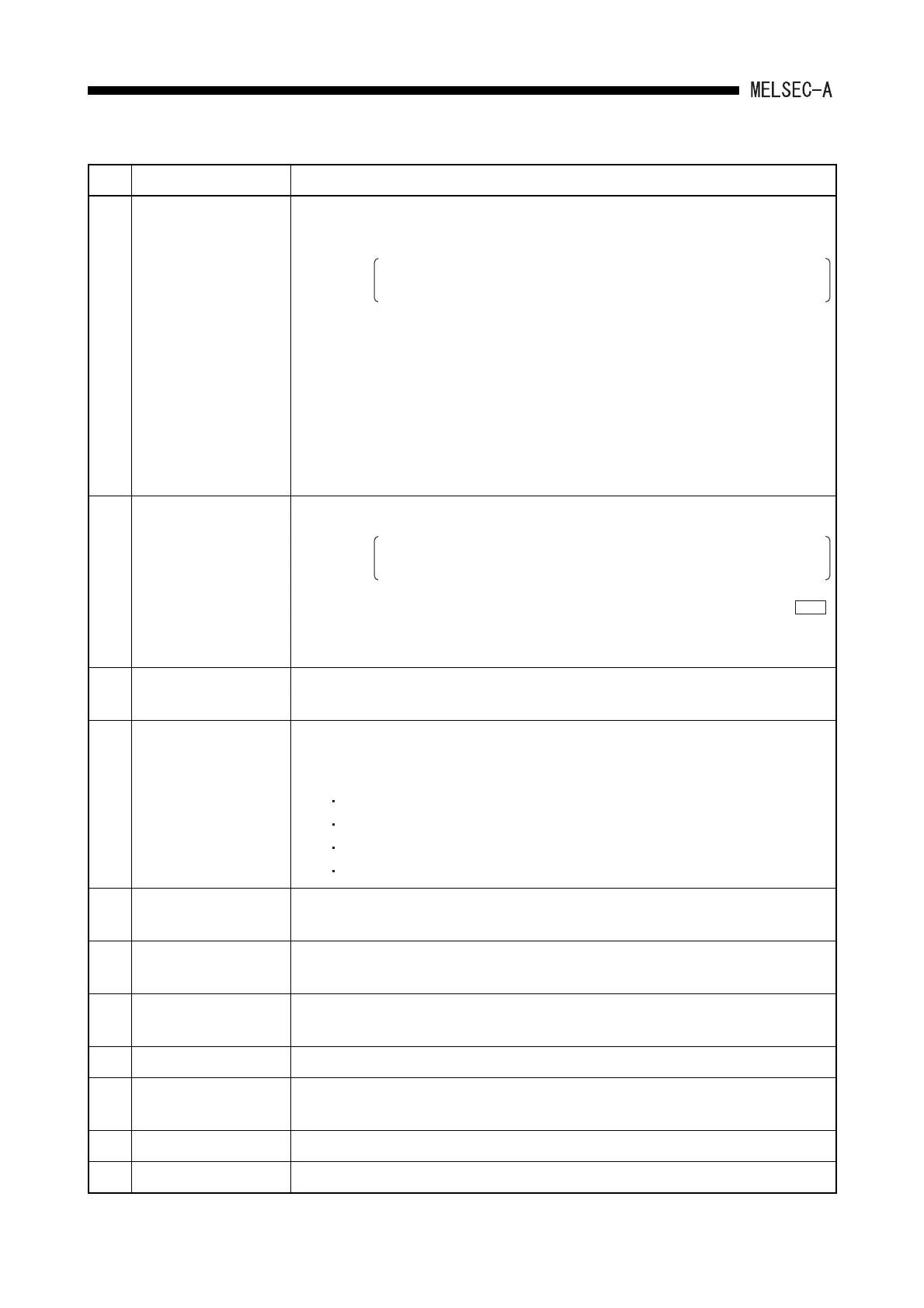
No. Name Description
(2) "RUN" LED
• ON: RUN/STOP key switch is in the "RUN" position, and the sequence
program operation is being executed.
In case of an error which continues the operation of sequence program
occurs (refer to Section 11.3), the LED remains ON.
•OFF:
• Flickering:
The "RUN" LED turns off in the following cases:
• The RUN/STOP switch is set to "STOP".
• Remote STOP is being performed.
• Remote PAUSE is being performed.
The "RUN" LED flickers in the following cases:
• An error which causes operation of the sequence program to stop has
been detected by self-diagnostics.
During latch clear operation
(3) "ERROR" LED
• ON: An error has been detected by self-diagnostics.
When an error which has been set to LED OFF in the priority order
setting of the LED indication is detected, the LED remains OFF.
•OFF:
• Flickering:
When failure of the system or target device is detected by normal or
instruction.
Annunciator (F) is turned on in the sequence program.
(4) RS-422 connector
• Connector to write/read, monitor and test the main program with peripheral device.
• Cover it with a lid when no peripheral device is to be connected.
(5) Cover
• Protective cover for printed-circuit board of CPU module, memory cassette, RS-422
connector, battery, etc.
• Open the cover to perform the following operations:
Installation and removal of the memory cassette
Setting DIP switches
Connecting the battery to the connector
Battery replacement
(6)
Module mounting
screws
• Used to fix a module to the base unit.
(7) Battery
• For the retention of data for program, latch range devices and file registers (for
installation and removal of battery, refer to Section 7.2)
(8) Dip switch
• The switch to set whether memory protect is enabled or not, when built in RAM is
used. (Refer to Section 4.5.2 for details of the setting.)
(9) Battery connector • For the connection with the connector on the battery side.
(10)
Memory cassette
installing connector
• Connector to install a memory cassette (It automatically enters into ROM operation
when a memory cassette is installed.)
(11) Hardware version • Hardware version seal of CPU module
(12) Software version • Software version seal of CPU module
CHK
 Loading...


