2.
SYSTEM
CONFIGURATKlN
/MELSEC--
2.
SYSTEM
CONFIGURATION
2.1
Introduction
to
the
AD71
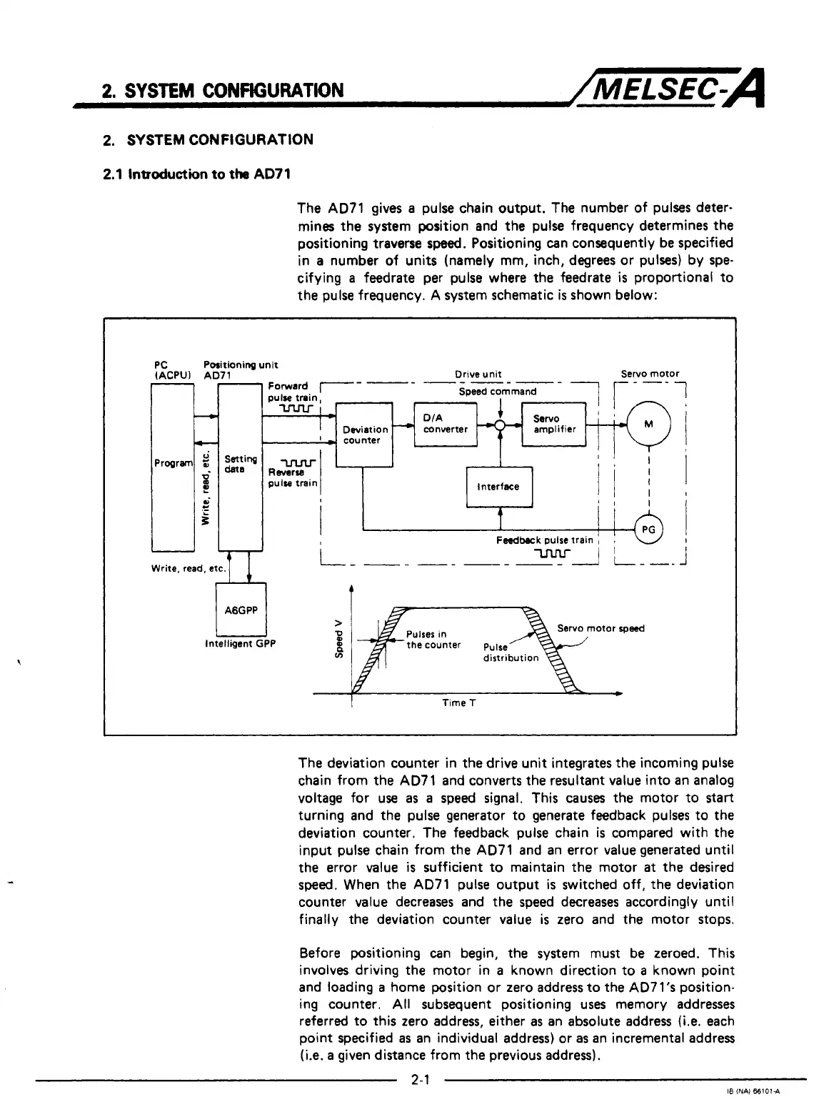
The AD71 gives
a
pulse chain output. The number of pulses deter-
mines the system position and the pulse frequency determines the
positioning traverse
speed.
Positioning can consequently be specified
in
a
number of units (namely mm, inch, degrees or pulses) by spe-
cifying
a
feedrate per pulse where the feedrate
is
proportional to
the pulse frequency. A system schematic
is
shown below:
'C
ACPUl AI
PC
e
thing unit
'1
Drive unit Servo motor
~lse train,
Speed command
r
-
DIA
Deviation
converter
'
-
-1unter
AGGPP
>
Intelligent GPP
2
n
ln
it
'I
I
t
Feedback
pulse train
!
1
i
i
I
I
otor
rpwd
the counter pulse
Time
T
The deviation counter in the drive unit integrates the incoming pulse
chain from the AD71 and converts the resultant value into an analog
voltage for use
as
a
speed signal. This causes the motor to
start
turning and the pulse generator to generate feedback pulses to the
deviation counter. The feedback pulse chain
is
compared with the
input pulse chain from the AD71 and an error value generated until
the error value
is
sufficient to maintain the motor
at
the desired
sped.
When the AD71 pulse output
is
switched off, the deviation
counter value decreases and the speed decreases accordingly until
finally the deviation counter value
is
zero and the motor stops.
Before positioning can begin, the system must be zeroed. This
involves driving the motor in
a
known direction to
a
known point
and loading
a
home position or zero address to the AD7l's position-
ing counter.
All
subsequent positioning uses memory addresses
referred to this zero address, either
as
an absolute address
(Le.
each
point specified
as
an individual address) or
as
an incremental address
(i.e.
a
given distance from the previous address).
2-1
I8
(NAI
661014

 Loading...


