6.
PROGRAMMING
~/MELSEC-A
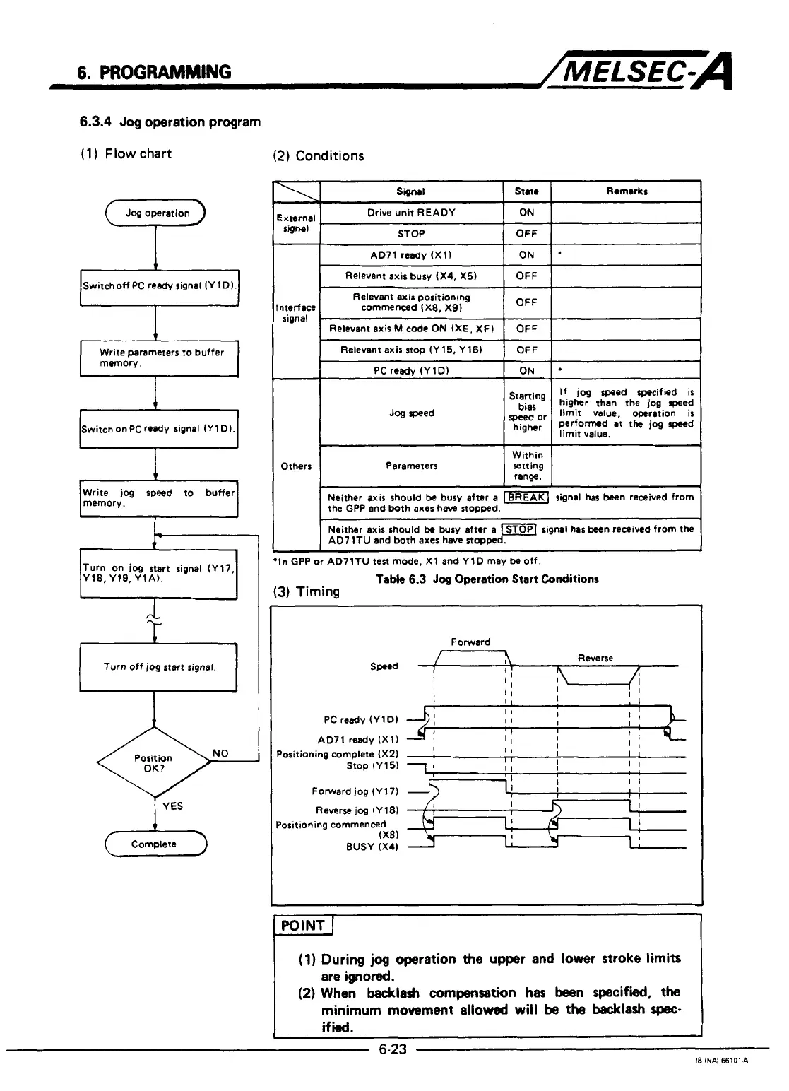
6.3.4
Jog
operation program
(1
)
Flow
chart
(2)
Conditions
Signal
Star
ixternal
,
Drive unit READY
ON
STOP
OFF
signal
(7
Jog
operation
I
Relevant axisbury (X4,
X5)
I
OFF
I I
/Switchoff PC ready signal (YlD).!
Relevant axis positioning
nterface commenced IXB, X9)
signal
Relevant axis
stop
(Y 15, Y 16)
PC
ready IYlD)
Write parameters
to
buffer
memory.
I
starting
higher than the jog speed
bias
If
jog speed specified is
limit value, operation is
speed
or
higher
perfomd
at
thc
Speed
limit value.
+
Switch on
PC
ready
signal
IY
1
D).
I
Write jog speed to buffer
memory.
1
Jog
wed
~~ ~ ~~
~~~
Within
Parameters
Letting
range.
the GPP and both axes have stopped.
Neither axis should
be
busy after a
(-1
signal has been received from
Neither axis should be busy after
a
signal has been received from the
AD7lTU and both axes have stopped.
Others
I
f
+In
GPP or AD7lTU
test
mode, X1 and YlD may be off.
Table
6.3
Jog
Operation
Start
Conditions
(3)
Timing
Turn on
jog
stert signal (Y17,
Y18, Yl9, YlA).
Forward
PC
ready (YlDl
AD71 ready (X11
Positioning complete (X21
Stop (Y15)
Forward jog (Y17)
Reverse
jog
(Y18)
(23
Complete
Positioning commenced
(X8)
BUSY (X41
(1)
During
jog
operation the upper and lower stroke limits
are ignored.
(2)
When
backlash
compensation
has
been specified, the
minimum
movement
allowed
will
be
the
backlaah
spec-
if
ied.
i
6-23
?
I
18
INAI
66101.A
1
I
I
4

 Loading...


