ENGINE
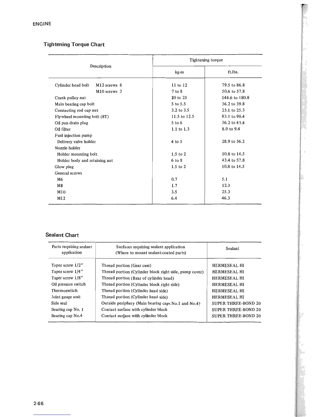
Tightening Torque
Chart
Tightening torque
2·66
Description
Cylinder head bolt M12 screws 8
M10
screws 3
Crank pulley nut
Main bearing cap bolt
Connecting rod cap
nut
Flywheel mounting bolt (8T)
Oil pan drain plug
Oil filter
Fuel injection pump
Delivery valve holder
Nozzle holder
Holder mounting bolt
Holder body and retaining nut
Glow plug
General screws
M6
M8
M10
M12
Sealant Chart
kg·m
11
to 12
7 to 8
:W
to
25
5 to 5.5
3.2 to 3.5
11.5 to 12.5
5 to 6
1.1
to 1.3
4 to 5
1.5
to
2
6 to 8
1.5
to 2
0.7
1.7
3.5
6.4
Parts requiring sealan t
application
Surfaces requiring sealant application
(Where to mount sealant·coated parts)
TDper
screw
1/2"
Taper screw
1/4"
Taper screw
1/8"
Oil
pressure switch
Thermoswitch
Joint gauge unit
Side seal
Bearing cap
No,
1
Bearing cap No.4
Thread portion (Gear case)
Thread portion (Cylinder block right side, pump cover)
Thread portion (Rear
of
cylinder head)
Thread portion (Cylinder block right side)
Thread portion (Cylinder head side)
Thread portion (Cylinder head side)
Outside periphery (Main bearing caps No.1 and No.4)
Contact surface with cylinder block
Contact surface with cylinder block
ft.1bs.
79.5 to 86.8
50.6 to 57.8
144.6 to 180.8
36.2 to 39.8
23.1 to 25.3
83.1 to
90.4
36.2 to 43.4
8.0 to 9.4
28.9 to 36.2
10.8 to 14.5
43.4 to 57.8
10.8 to 14.5
5.1
12.3
25.3
46.3
Sealant
HERMESEAL
HI
HERMESEAL
HI
HERMESEAL
HI
HERMESEAL
HI
HERMESEAL
HI
HERMESEAL
HI
SUPER THREE·
BOND
20
SUPER THREE·BOND 20
SUPER THREE·BOND 20
 Loading...