MN003109A01_aa
1-2 Introduction Mobile Radio Description
Figure 1-9 and Figure 1-10, show the basic dimensions of the remote mount transceiver trunnion
APX mobile radio.
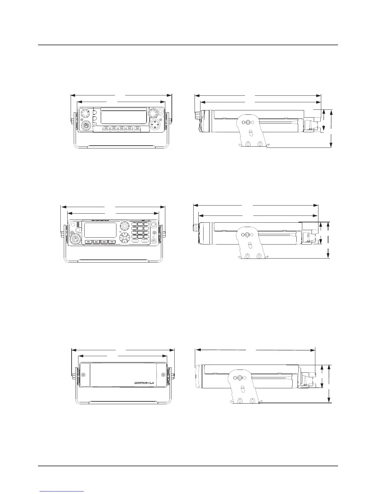
Figure 1-3. Front View of O3 Control
Head with Coiled Cable
Figure 1-4. Side View of O3 Control
Head with Coiled Cable
Figure 1-5. Front View of O5 Control Head
Attached to APX 8500
Mid Power Dash Mount Transceiver and Trunnion
Figure 1-6. Side View of O5 Control Head
Attached to APX 8500 Mid Power
Dash Mount Transceiver and Trunnion
Figure 1-7. Front View of O7 Control Head
Attached to APX 8500 Mid Power Dash Mount
Transceiver and Trunnion
Figure 1-8. Side View of O7 Control Head Attached
to APX 8500 Mid Power Dash Mount Transceiver
and Trunnion
Figure 1-9. Front View of Remote Mount and
Trunnion
Figure 1-10. Side View of Remote Mount and
Trunnion
206
178
Draft
 Loading...


