MN003109A01_aa
Standard Configurations Power Cables (Transceiver and Control Head) 2-37
2.3 Power Cables (Transceiver and Control Head)
Route the RED power cable from both the radio and the control head to the vehicle battery
compartment, using accepted industry methods and standards. Be sure to grommet the firewall hole
to protect the cable. Remove the 15-amp (part number 6580283E06), 20-amp (part number
6580283E07) or 30-amp (part number 6580283E09) fuse from the fuseholder and connect the red
lead of the radio power cable to the positive battery terminal using the hardware provided as shown
in Figure 2-43 and Figure 2-44. Connect the black lead to a convenient solid chassis ground point.
DO NOT connect the black lead directly to the battery negative terminal.
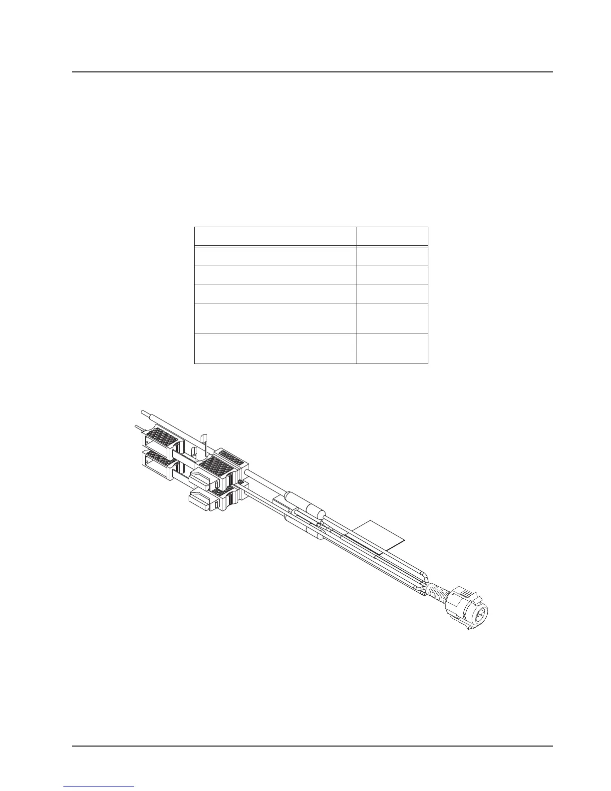
2.3.1 O2, O5, O7 or O9 Control Head Power Cables
Figure 2-43. HKN6188_ Power Cable with External Speaker Connector
Table 2-8. Power Cables
Description Part Number
Mid Power Dash Mount HKN4191_
Mid Power Remote Mount HKN4192_
High Power Remote Mount HKN6110
O5, O7, and O9 Remote Control
Head Power Cable - Mid Power
HKN6188_
O5, O7, and O9 Remote Control
Head Power Cable - High Power
HKN6188_ or
HKN6188_
Draft
 Loading...


