MN003109A01_aa
Standard Configurations Radio Mounting 2-23
2.2.1 Dash Mount with Trunnion - Mid Power
1. Select the location to mount your radio on the transmission hump (see Figure 2-25) or under
the dash (see Figure 2-26)
NOTE: When mounting the trunnion on the transmission hump take care that the transmission
housing is not affected. Plan your installation ensuring enough room for the Accessory
connector and cable in the back of the radio.
2. Using the trunnion mounting bracket as a template, mark the positions of the holes on the
mounting surface. Use the innermost four holes for a curved mounting surface such as the
transmission hump, and the four outmost holes for a flat surface such as under the dash.
3. Center punch the spots you have marked and realign the trunnion in position.
4. Secure the trunnion mounting bracket with the four self-drilling screws provided
(see Figure 2-25 and Figure 2-26).
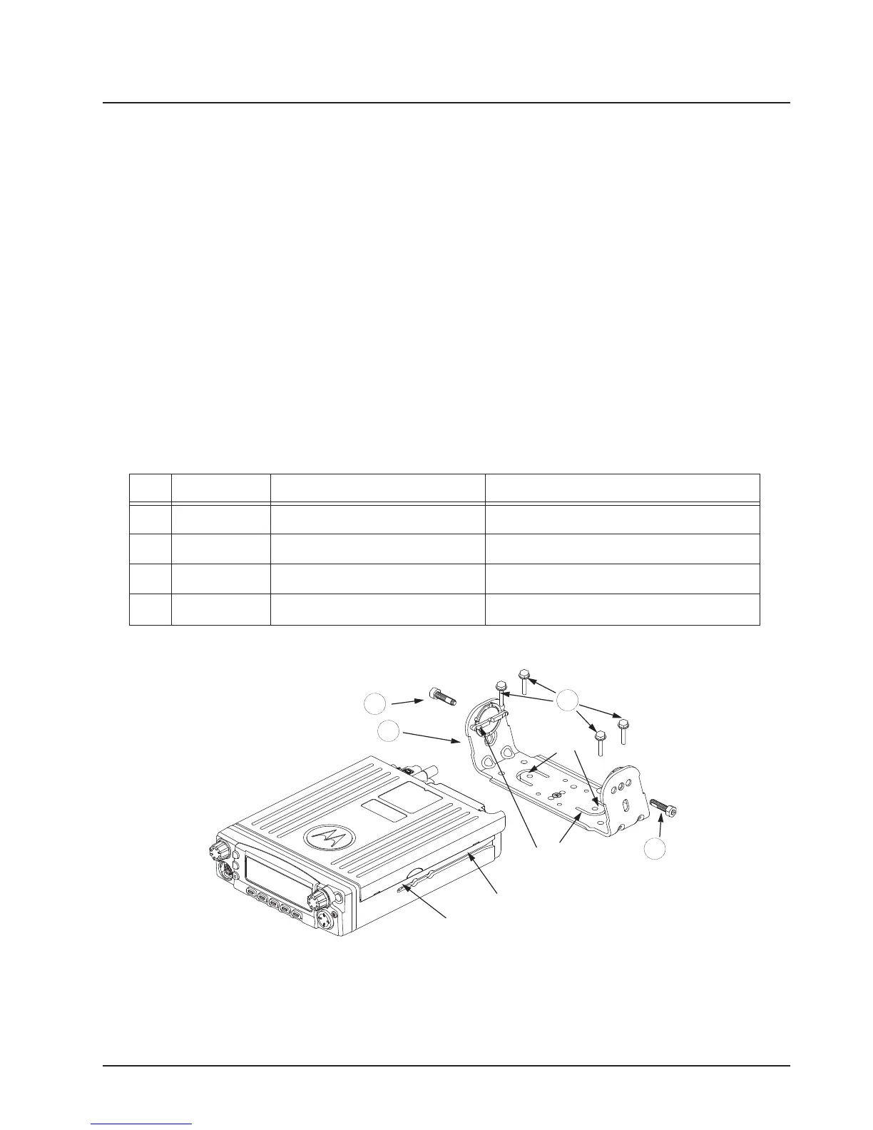
5. Ensure that the plastic guides are aligned (horizontal) to the grooves of the trunnion. Slide the
radio into the grooves until it snaps into place (see Figure 2-26).
Figure 2-25. Below Dash Trunnion Mounting
Table 2-6. +LJKMid Power Trunnion Kit
Tabs
Threaded Hole
for Screw
Groove
Plastic
Guides
1
3
2
1
Item Part Number Description High/Mid Power Transceiver
1 0371859H01 Trunnion Mounting Screw APX 8500
2 0312002B14 Self-Drilling Tapping Screw APX 8500
3 HLN7002_ Mackinaw Trunnion Hardware Kit APX 8500
4
HLN7003_
Mackinaw Trunnion Hardware Kit APX 8500
Draft
 Loading...


