MN003109A01_aa
3-4 Universal Relay Controller Installation O7/O9 Universal Relay Controller Cable Assembly
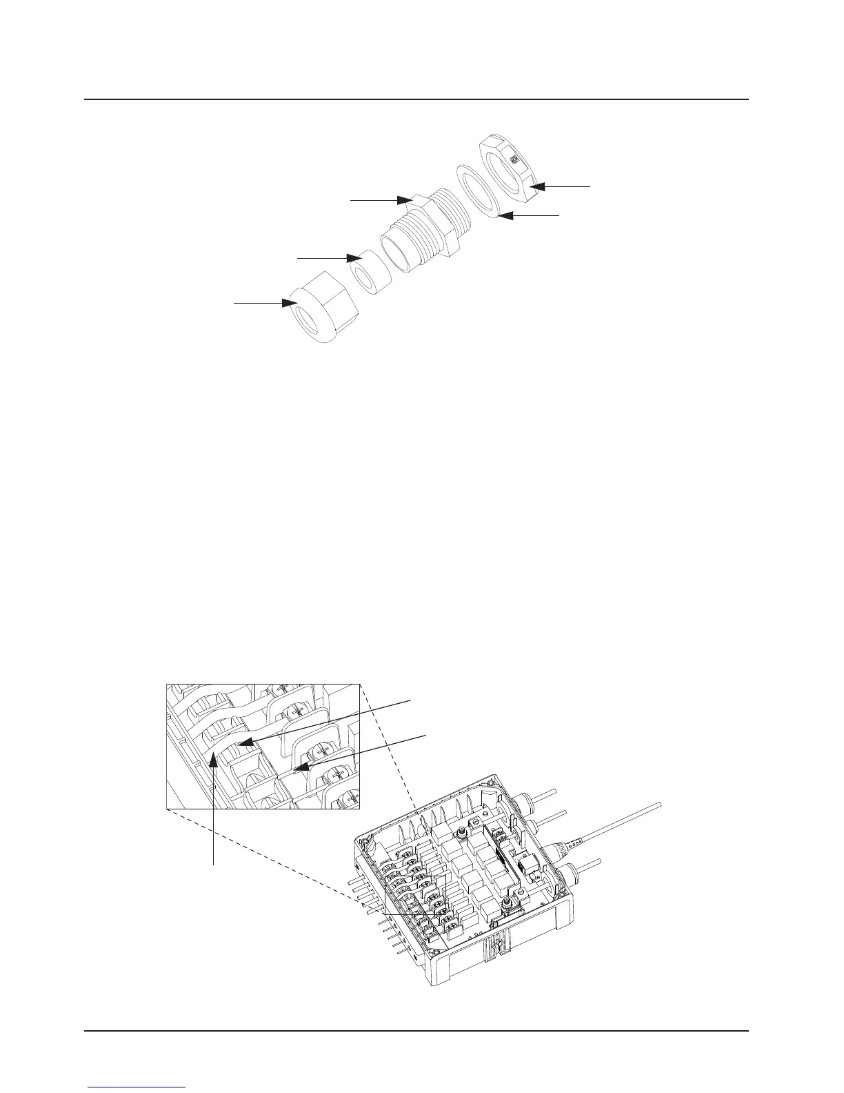
Figure 3-4. Cable Gland Assembly with Gasket
3.2.3 Wires
1. Assemble the wires into the lightbar gasket retainer and lightbar gasket. The URC can
support lightbars through control wires with outer diameter ranging from
1.52 mm to 3.77 mm (0.06” to 0.148”), with wire gages ranging from AWG 12 – 20.
2. Each individual loose wire (prior to stripping off the wire jacket) needs to be inserted one at a
time through the chassis. Ensure the lightbar wire is straight before inserting the wire into the
chassis. Each wire is sealed individually by the radial gasket seal. When a thick wire that is
AWG 14 wire or wire OD > 2.90 mm is inserted through the chassis, there is potential torn at
the rubber gasket. Remove the rubber gasket residual and continue to the next step.
3. Thin wires 2.5 mm and below should be dressed into the retention feature using a black stick
(see Figure 3-5); thick wires above 2.5 mm should be routed above the retention feature.
Strip off the wire until 7.94 mm (5/16”) after the wire is inserted into the URC, and install the
wire into respective lightbar terminal block.
4. Cover the lightbar gasket retainer's hole with seal, gasket and ground cable gland, if no wire
is inserted.
Figure 3-5. Wires Installation
Counter Nut
Gasket, Cable Gland
Neoprene Seal
Cap Nut
Cable Gland
WIRE RETENTION FEATURE
LIGHTBAR WIRE WITH DIAMETER
2.5 mm AND BELOW
LIGHTBAR WIRE
WITH DIAMETER
ABOVE 2.5 mm
Draft
 Loading...


