Overview
Theory of Operation 5C.3-1
1.0 Overview
This section provides a detailed theory of operation for the radio and its components.
The main radio is a single board design, consisting of the transmitter, receiver, and controller
circuits.
The main board is designed to accept one additional option board. This may provide functions such
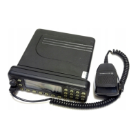
as secure voice/data or DTMF decoder. The control head is mounted directly on the front of the
radio or connected via an extension cable in remote mount operation. The control head contains a
speaker, LED indicators, a microphone connector, buttons and dependent of radio type, a display.
These provide the user with interface control over the various features of the radio.
In addition to the power cable and antenna cable, an accessory cable can be attached to a
connector on the rear of the radio. The accessory cable provides the necessary connections for
items such as external speaker, emergency switch, foot operated PTT, ignition sensing, etc.
2.0 Open Controller
2.1 General
The radio controller consists of 4 main subsections:
■
■■
Digital Control
■
■■
Audio Processing
■
■■
Power Control
■
■■
Voltage Regulation
The digital control section of the radio board is based upon an open architecture controller
configuration. It consists of a microprocessor, support memory, support logic, signal MUX ICs, the
On/Off circuit, and general purpose Input/Output circuitry.
The controller uses the Motorola 68HC11K1 microprocessor (U0101). In addition to the
microprocessor, the controller has 3 external memory devices. The 3 memory devices consist of a
32 Kbyte SRAM (U0103), a 256 Kbyte FLASH EEPROM (U0102), and a 4kbyte EEPROM (U0104).
Note: From this point on the 68HC11K1 microprocessor will be referred to as µP or K1µP.
References to a control head will be to the N3 radio model - control head with display.
2.2 Voltage Regulators
Voltage regulation for the controller is provided by 3 separate devices; U0631 (LP2951CM) +5V,
U0601 (LM2941T) +9.3V, and UNSW 5V (a combination of R0621 and VR0621). An additional
regulator is located in the RF section.
Voltage regulation providing 5V for the digital circuitry is done by U0631. Input and output capacitors
(C0631/C0632 and C0633-C0635) are used to reduce high frequency noise and provide proper
operation during battery transients. This regulator provides a reset output (pin 5) that goes to 0 volts
if the regulator output goes out of regulation. This is used to reset the controller to prevent improper
operation. Diode D0631 prevents discharge of C0632 by negative spikes on the 9V3 voltage
5
 Loading...