47
Overview of Components
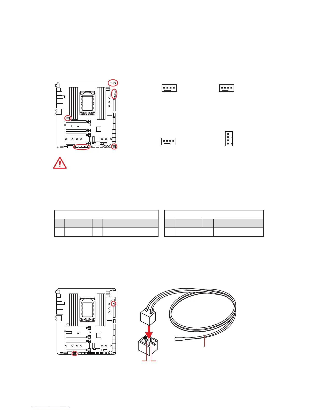
CPU_FAN1, PUMP_FAN1, SYS_FAN1~5, EXT_FAN1~3: Fan
Connectors
Fan connectors can be classified as PWM (Pulse Width Modulation) Mode or DC Mode.
PWM Mode fan connectors provide constant 12V output and adjust fan speed with
speed control signal. DC Mode fan connectors control fan speed by changing voltage.
This motherboard can automatically detect PWM and DC mode. However, you can
follow the instruction below to adjust the fan connector to PWM or DC Mode manually.
PWM Mode pin definition
1 Ground 2 +12V
3 Sense 4 Speed Control Signal
DC Mode pin definition
1 Ground 2 Voltage Control
3 Sense 4 NC
Pin definition of fan connectors
T_SEN1~3: Thermal Sensor Connectors
These connectors allow you to connect the thermistor cable and use it to monitor the
temperature of the detection point.
Thermistor cable
GND
Sense
Important
y
You can switch between PWM mode and DC mode and adjust fan speed in BIOS >
HARDWARE MONITOR.
y
Make sure fans are working properly after switching the PWM/ DC mode.
Default DC Mode fan connectors
1
CPU_FAN1
(Default : Auto-detection
Mode)
1
SYS_FAN5/ EXT_FAN3
1
PUMP_FAN1
(Default : PWM Mode)
1
SYS_FAN1/ SYS_FAN2/ SYS_
FAN3/ SYS_FAN4/ EXT_FAN1/
EXT_FAN2
 Loading...