54
Onboard LEDs
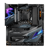
JPWRLED1: LED light demonstration power input connector
This connector is used by retailers to demonstrate onboard LED lights.
JPWRLED1 - LED power input
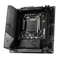
Debug Code LED
Debug Code LED
The Debug Code LED displays progress and error codes during and after POST. Refer
to the Debug Code LED table for details.
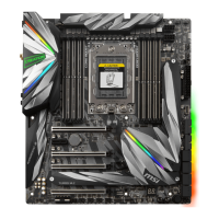
Hexadecimal Character Table
Hexadecimal 0 1 2 3 4 5 6 7 8 9 A B C D E F
Debug Code
LED display
0 1 2 3 4 5 6 7 8 9 A B C D E F
Boot Phases
Security (SEC) – initial low-level initialization
Pre-EFI Initialization (PEI) – memory initialization
Driver Execution Environment (DXE) – main hardware initialization
Boot Device Selection (BDS) – system setup, pre-OS user interface & selecting a
bootable device (CD/DVD, HDD, USB, Network, Shell, …)
 Loading...