Chapter 2
2-12
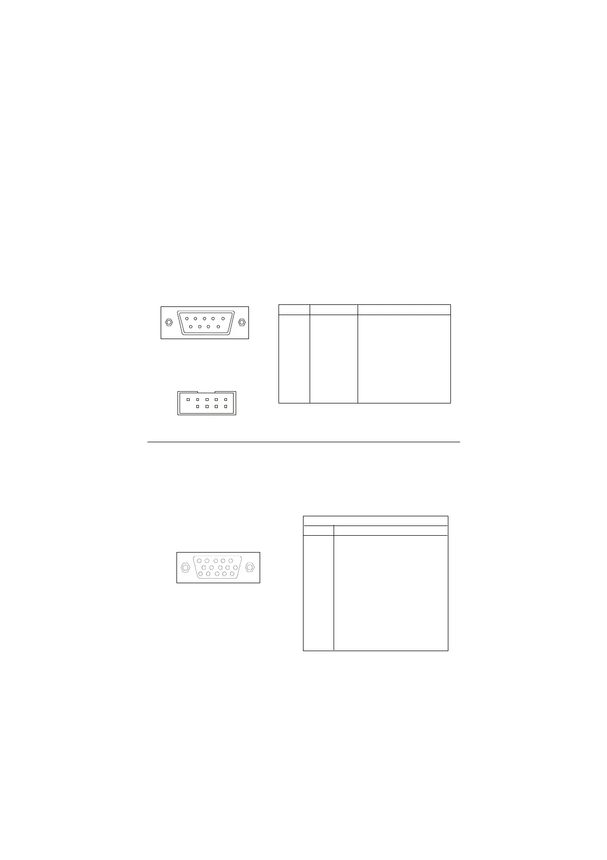
Serial Port Connector: COM A & COM 2
The mainboard has two 9-pin serial port connectors, one (COM A) in the back
panel and one (COM 2) on-board. You can attach a serial mouse or other serial
devices to them.
9-Pin Male DIN Connectors
1 2 3 4 5
6 7 8 9
COM A
PIN SIGNAL DESCRIPTION
1 DCD Data Carry Detect
2 SIN Serial In or Receive Data
3 SOUT Serial Out or Transmit Data
4 DTR Data Terminal Ready
5 GND Ground
6 DSR Data Set Ready
7 RTS Request To Send
8 CTS Clear To Send
9 RI Ring Indicate
Pin Definition
VGA DB 15 Pin Connector
The mainboard provides one DB 15-pin female connector to connect a VGA
monitor.
DB 15-Pin Female Connector
5 1
15 11
Analog Video Display Connector (DB-15S)
PIN SIGNAL DESCRIPTION
1 Red
2 Green
3 Blue
4 Not used
5 Ground
6 Ground
7 Ground
8 Ground
9 Power
10 Ground
11 Not used
12 SDA
13 Horizontal Sync
14 Vertical Sync
15 SCL
Pin Definition
COM 2
 Loading...