2-18
MS-7145 M-ATX Mainboard
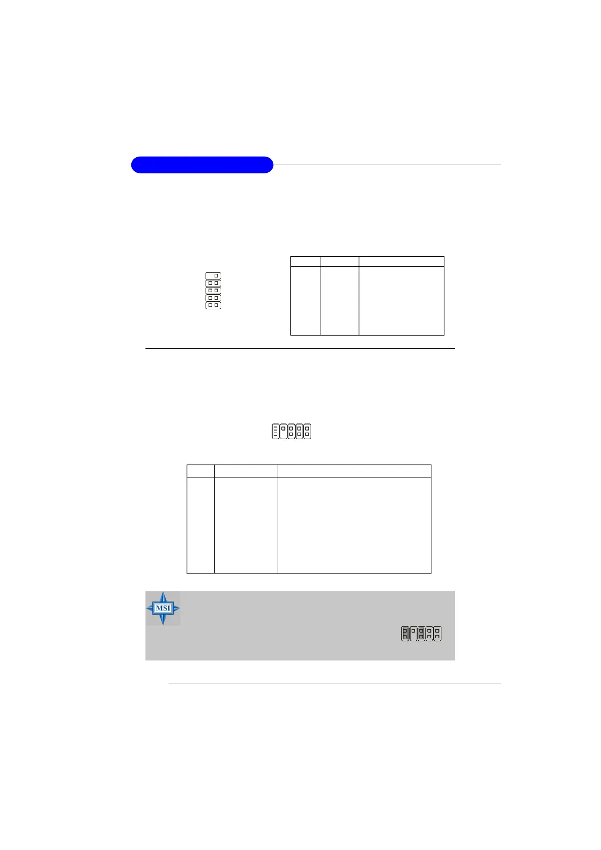
Serial Port Header: JCOM2 (Optional)
The mainboard offers one 9-pin header as serial port. The port is a 16550A
high speed communication port that sends/receives 16 bytes FIFOs. You can attach
a serial mouse or other serial device directly to it.
Pin Definition
PIN SIGNAL DESCRIPTION
1 DCD Data Carry Detect
2 SIN Serial In or Receive Data
3 SOUT Serial Out or Transmit Data
4 DTR Data Terminal Ready)
5 GND Ground
6 DSR Data Set Ready
7 RTS Request To Send
8 CTS Clear To Send
9 RI Ring Indicate
JCOM2
1
5
6
9
MSI Reminds You...
If you don’t want to connect to the front audio header,
pins 5 & 6, 9 & 10 have to be jumpered in order to have
signal output directed to the rear audio ports. Otherwise,
the Line-Out connector on the back panel will not
function.
5
6
10
9
Front Panel Audio Connector: JAUDIO1
The JAUD1 front panel audio connector allows you to connect to the front
panel audio and is compliant with Intel
®
Front Panel I/O Connectivity Design Guide.
JAUDIO1
1
2
9
10
PIN SIGNAL DESCRIPTION
1 AUD_MIC Front panel microphone input signal
2 AUD_GND Ground used by analog audio circuits
3 AUD_MIC_BIAS Microphone power
4 AUD_VCC Filtered +5V used by analog audio circuits
5 AUD_FPOUT_R Right channel audio signal to front panel
6 AUD_RET_R Right channel audio signal return from front panel
7 HP_ON Reserved for future use to control headphone amplifier
8 KEY No pin
9 AUD_FPOUT_L Left channel audio signal to front panel
10 AUD_RET_L Left channel audio signal return from front panel
Pin Definition
 Loading...